The problem with the neopixel colors was found and corrected. We had to change the indications in the code from NEO_GRB to NEO_RGBW:
![]()

A Student Project of the HCI Group | Bauhaus-Universität Weimar
The problem with the neopixel colors was found and corrected. We had to change the indications in the code from NEO_GRB to NEO_RGBW:
![]()
Even though the code was working properly in the Neopixel strip, when we uploaded the code to the Neopixels we solder, they were not working correclty, the should light in one color but instead of that, each Neopixel shines in a different color and the programmed light pattern is not working. We are trying to find out the problem.
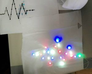
Neopixel shining in different colors

Soldered Neopixels
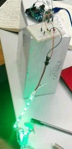
Neopixel srip
CODE:
#include <Adafruit_NeoPixel.h>
#ifdef __AVR__
 #include <avr/power.h>
#endif

#define PIN 6

// Parameter 1 = number of pixels in strip
// Parameter 2 = Arduino pin number (most are valid)
// Parameter 3 = pixel type flags, add together as needed:
// NEO_KHZ800 800 KHz bitstream (most NeoPixel products w/WS2812 LEDs)
// NEO_KHZ400 400 KHz (classic 'v1' (not v2) FLORA pixels, WS2811 drivers)
// NEO_GRB Pixels are wired for GRB bitstream (most NeoPixel products)
// NEO_RGB Pixels are wired for RGB bitstream (v1 FLORA pixels, not v2)
// NEO_RGBW Pixels are wired for RGBW bitstream (NeoPixel RGBW products)
Adafruit_NeoPixel strip = Adafruit_NeoPixel(60, PIN, NEO_RGBW + NEO_KHZ800);

// IMPORTANT: To reduce NeoPixel burnout risk, add 1000 uF capacitor across
// pixel power leads, add 300 - 500 Ohm resistor on first pixel's data input
// and minimize distance between Arduino and first pixel. Avoid connecting
// on a live circuit...if you must, connect GND first.

void setup() {
 // This is for Trinket 5V 16MHz, you can remove these three lines if you are not using a Trinket
 #if defined (__AVR_ATtiny85__)
 if (F_CPU == 16000000) clock_prescale_set(clock_div_1);
 #endif
 // End of trinket special code


 strip.begin();
 strip.show(); // Initialize all pixels to 'off'
}

void loop() {
 // Some example procedures showing how to display to the pixels:
 colorWipe(strip.Color(255, 0, 0), 50); // Red
 colorWipe(strip.Color(0, 255, 0), 50); // Green
 colorWipe(strip.Color(0, 0, 255), 50); // Blue
//colorWipe(strip.Color(0, 0, 0, 255), 50); // White RGBW
 // Send a theater pixel chase in...
// theaterChase(strip.Color(127, 127, 127), 50); // White
 // theaterChase(strip.Color(127, 0, 0), 50); // Red
 // theaterChase(strip.Color(0, 0, 127), 50); // Blue

 //rainbow(20);
 // rainbowCycle(20);
 // theaterChaseRainbow(50);
}

// Fill the dots one after the other with a color
void colorWipe(uint32_t c, uint8_t wait) {
 for(uint16_t i=0; i<strip.numPixels(); i++) {
 strip.setPixelColor(i, c);
 strip.show();
 delay(wait);
 }
}


//Theatre-style crawling lights.
void theaterChase(uint32_t c, uint8_t wait) {
 for (int j=0; j<10; j++) { //do 10 cycles of chasing
 for (int q=0; q < 3; q++) {
 for (uint16_t i=0; i < strip.numPixels(); i=i+3) {
 strip.setPixelColor(i+q, c); //turn every third pixel on
 }
 strip.show();

 // delay(wait);

 for (uint16_t i=0; i < strip.numPixels(); i=i+3) {
 strip.setPixelColor(i+q, 0); //turn every third pixel off
 }
 }

 }
}

// Input a value 0 to 255 to get a color value.
// The colours are a transition r - g - b - back to r.
uint32_t Wheel(byte WheelPos) {
 WheelPos = 255 - WheelPos;
 if(WheelPos < 85) {
 return strip.Color(255 - WheelPos * 3, 0, WheelPos * 3);
 }
 if(WheelPos < 170) {
 WheelPos -= 85;
 return strip.Color(0, WheelPos * 3, 255 - WheelPos * 3);
 }
 WheelPos -= 170;
 return strip.Color(WheelPos * 3, 255 - WheelPos * 3, 0);
}
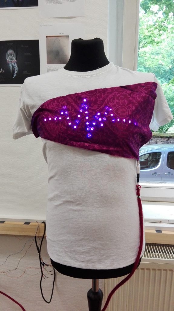
Today Jeong and me were thinking about the costume design. We decided to use neopixels and locate them in the chest of the performer. At the beginning we did not know which neopixel pattern could be the best. After a while we came up with an idea. We decided to make the shape of a heartbeat. We think this shape match perfectly with the theme of performance.
For some reason video editing programs tend to place a black frame at the end of the rendered clip. I really don’t know why, but that seems to be the usual thing. In my case that is kind of annoying, due to the fact, that I want to loop the video in unity.
After checking out several editing softwares, I ended up in the Ubuntu terminal:
ffmpeg, a command line video editor helps!
Use the first command to make your .mp4 to thousands of .jpg’s.
ffmpeg -i video.mp4 -qscale 0 scene%05d.jpg
By hand, you can easily delete the last frame…
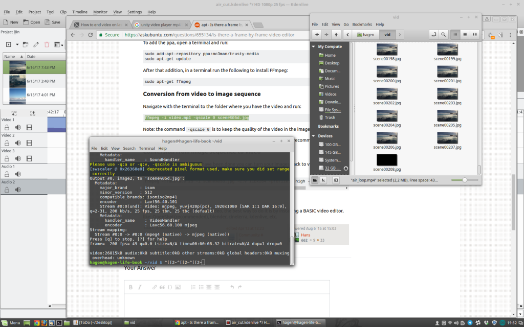
With the second command, you can take all your frames back into a .mp4.
ffmpeg -framerate 25 -i scene%05d.jpg -c:v libx264 -profile:v high -crf 20 -pix_fmt yuv420p newvideo.mp4Than you end up with a mp4, without a black frame at the end! Such a nice work-around, Cheers!
I found a couple of webpages where we can apparently free Download clips that may be helpful for the performance
Weapons-sound:
http://www.audiomicro.com/free-sound-effects/free-guns-and-weapons
Fight-sound:
https://www.freesoundeffects.com/free-sounds/fight-sounds-10034/
Scream-sound:
http://soundbible.com/tags-scream.html
Muezzin:
http://freesound.org/people/AcousticYorick/downloaded_sounds/
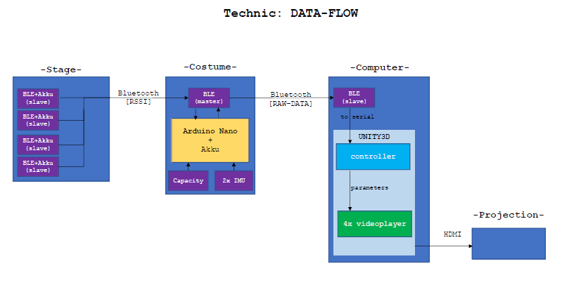
A short status-update:
the original plan:
Lucas primary developed the BLE(Stage)->Arduino(Costume) part:
We decided to work with the HM-10 modules, or so we thought. After some frustrating hours of not getting stuff to work, I noticed we don’t actually have HM-10 modules infront of us but rather HM-10 CC2541 modules, which are copys of the original. There is a diffrence however, all the At-commands have to end with „\r\n“ and the „?“ ending does not exist.
After figuring that out I looked up all the At-commands that the module offers. Nothing usefull to be found for our project, so I tryed uploading the original HM-10 firm-software to the CC2541. For this I took a look into this repository and the manufecturer site jnhuamao. I got myself the arduino code from the git-repository and uploaded it onto my Arduino Uno R3. Then I downloaded the CCLoader_x86_64.exe. From the manifacturer site I downloaded firmsoftware V540. One can download the latest version V549 and instead of useing the „AT+DISI?“ command to search for Beacons RSSI, you could use „AT+DISA?“ to search for all devices RSSI. For a more specific insight, one should look into the patch loggs, since there were other small but handy changes. Never the less, since I wanted to scann for Beacons, there was no need to get a later version then V540.
Now all thats left is the Hardware aspect. For this I cut the BLE modul out of its case and connected the Arduino VCC to Modules VCC, GND to GND, D6 to DD, D5 to DC and D4 to Reset. Not knowing which pin is which I took a look into the datasheet of the BLE-module. Run the CCloader_x86_64.exe from command line like this: path/CCLoader_x86_64.exe <COM Port> <path/Firmware.bin> 0. Done, now I had the HM-10 software on the CC2541 with the commands I opted to use.
Now to the actuall task, scanning RSSI of Beacons around. For this the „AT+DISI?“ command is helpful, since it returns 5-parameters, of which the fifth is the RSSI value of the device specified by its MAC-Adress (parameter 4). For this Command to actually work I needed to configure the BLE-Module, by running these commands first: „AT+ROLE1“ asigning Master role, „AT+BAUD0“ setting same baud as both Serial ports, „AT+RESET“ restart to aply changes, „AT+SHOW1“ show name, „AT+IMME1“ set worktyp. For further insight, datasheet is your best friend. Now i am able to run the „AT+DISI?“ command. The resieved answer from the BLE-module now only has to be parsed and filterd (see code) and vola, we now resieve the RSSI values of our specified devices.
For the connection Arduino-BLE module see here. Only diffrence mySerial(2,3) changed to mySerial(12,14). Change circuit accordingly.
Source code: Arduino code
Phil focused on the Arduino(Costume)->Unity3D(Computer) part. At first, we intended to use BLE, to achieve a communication between costume and Unity3D. Unfortunately the combination of Unity3D/C#/Windows and BLE seems to be a kind of unexplored thing. I was not able to find a good solution. There are some libraries to use mobile(android, ios) BLE with Unity3D(which actually cost money), but that does not help us. So I dropped back to the Adafruit Feather and its Wifi-Module. Maybe the costume will be controlled by the Feather as our primary micro controller, or we stick with the Arduino Nano and attach a seperate Wifi-Module. We will decide about this later. The problem with the Feather is the number of analoge pins, exactly 1… Anyway I was able to set up a server in Unity and receive sensor values. The video’s intensity can already be manipulatet by the RSSI values. My next step is, to seperate the video-framerate by the feather’s send-rate. I will consider using an asynchronous connection. Furthermore I have to get the other video-manipulations working. I will probably make use of Video-Textures in Unity3D!
Source code: Unity3D code
The Feather-client-connection part can be found in Lucas Arduino-sketch.
And some more BLE Links..:
https://blog.bluetooth.com/proximity-and-rssi
https://shinesolutions.com/2014/02/17/the-beacon-experiments-low-energy-bluetooth-devices-in-action/
https://community.estimote.com/hc/en-us/articles/201302836-How-precise-are-Estimote-Beacons-
Our project technic has to cover all the way from input(sensor) to output (actuator). To give the actor freedom, we need a wireless transmission. For this we chose the following hardware, software and our interaction modle.
| Input |
|---|
| Sensors: |
|
| Microcontroller |
|
| Transmitter |
|
| Output |
|---|
| Receiver+Computation (pc) |
|
| Actuators (beamer, speaker) |
|
Concept:
The interaction idea is as follow. The „play“ is structurable into three parts: (1)Intro, (2)story/flashbacks, (3)Outro. Starting at (1), which is somewhat a basic projection state, all we are going to need is a way to switch to (2). Herefore a simple capasity sensor would be enough to signal the transition to (2).
Since (2) is the main interaction state or rather more the main objective for sensoric, we are going to have most hardware resulting from here. The basic setup is a rectangle out of BLE-Beacons in which the preformer is allowed to move. These four Beacons basicly represent the four flashbacks. So we now have a rectangle with a flashback asigned to each corner. For the projection, we are going to have one projectionspace on which we are going to project all flashbacks simultaneously, layering them over eachother so to speak. Since the flashbacks are asociable with a location, we are going to use this for our translation. Thought is, depending on the distance from preformer to flashback, the resulting trensformation of the projection is intensified or lowerd. So if the preformer closes distance to a corner, all his/her actions maniulate this corners falshback more then the others. Now the question would be how and in which way can the preformer manipulat the projection. Basic effect are going to be transparency, speed, color and brightness. These are going to be measured by onbody sensoric. For speed we are going to use an IMU located at the arm. This is going to be used for acceleration and tilt. The faster the preformer moves his/her arm in a cirtain direction, the faster the playspeed will get, vis versa for slowing down. An other IMU will be located on the back of the preformer. Once again with tilt and accereration to measure. This module will be responsible for color and/or brightness as to how the upperbody is located in space. If the preformer is bended forward(darker) or upright(lighter). In adition to the IMU on the back, we are also installing our cumpotational unit, the arduino nano plus the BLE-module. The BLE-module is going to be responsible for RSSI resival on comercial frequencies and the transmition of your data to our PC.
Lastly we are going to have to be able to switch to (3). Again our capacity sensor will have to fulfill the task.
We are currently trying to establisch a connection between our PC and our Arduino. For this we are trying to use a bluetooth transiever, the HC 05. In our first attempt, we useing the HC 05 as a receiver, which reads input data from our computer.
Hardware:
First things first, we need to setup our devises. Here the resistors are 100 Ohm each. This is due to the TX/RX needing 3.3V. Also keep in mind, that the RX goes to TX and vice versa.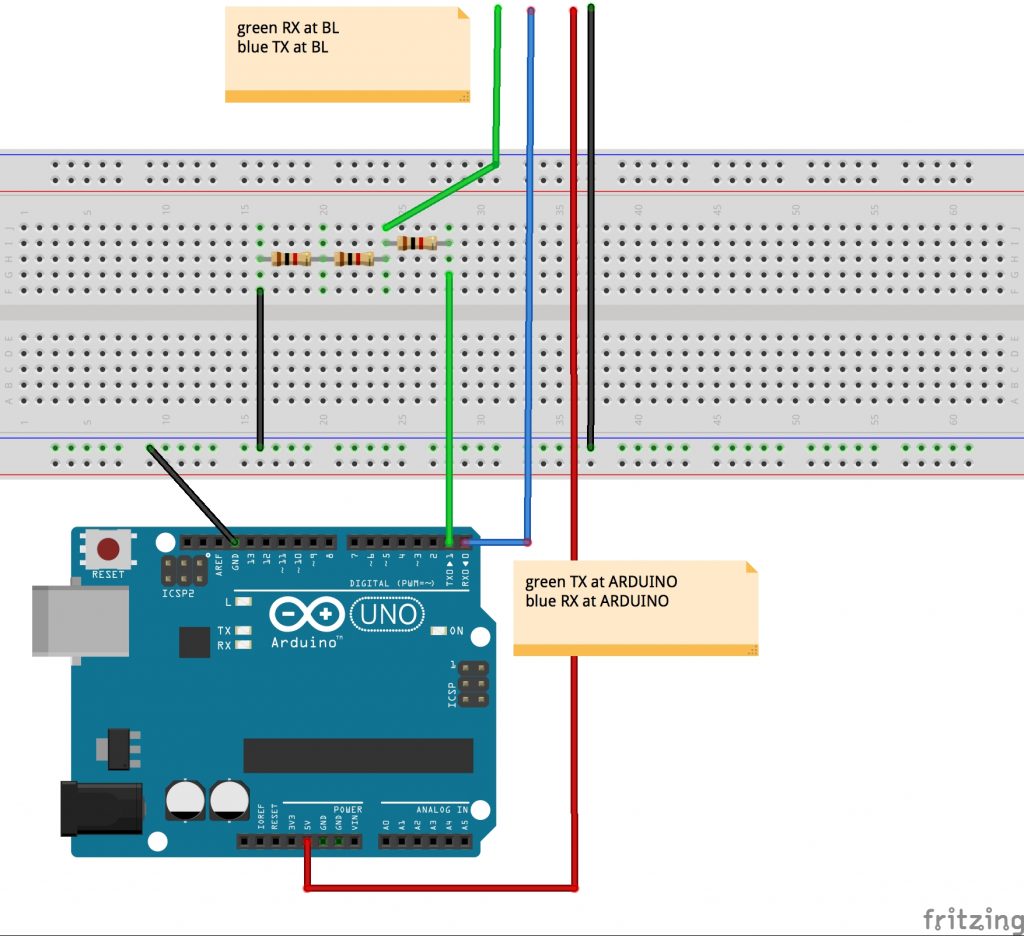
Once we’ve got the setup, its time for the software. Herefor we are useing Processing on PC (Win 10) to send and the Arduino IDE for the recieving arduino. Later on we are going to do it the other way around.
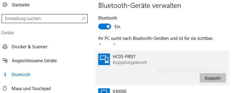
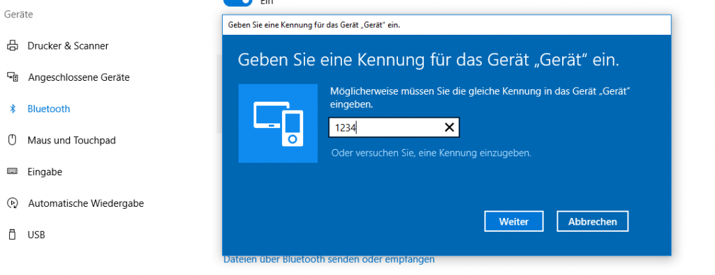
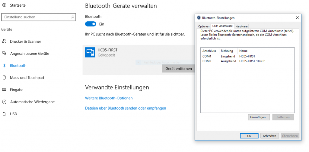
Step two would be pairing with the bluetooth device we just hooked up to the arduino. Under Win10 you can achieve it like follows:
Now we have a finnished setup and its time for some code. Since our first objektiv is sending data to our arduino, it needs to be able to recieve it. For this code to work move the TX pin to pin 8 and the RX pin to pin 7!
#include <SoftwareSerial.h>
SoftwareSerial mySerial(7, 8);

void setup() {
  Serial.begin(9600);
  mySerial.begin(9600);
}

void loop() {
  char to_read;

  //while there is a signal from our HC 5
  //print it!
  while (mySerial.available()) {
    to_read = mySerial.read();
    Serial.print(to_read);
  }
}
In the code above, the arduino recieves data via the Serialports und prints it. The counter part would be the PC sending data via Processing. This looks as follows:
import processing.serial.*;

//Serial port object:
Serial arduino;
final int  baudRate   = 9600;
final char delimiter = '\n';

void setup() {
  //list all the available serial ports:
  println("Available Serial Ports:");

  //Choose your Bluetooth port:
  printArray(Serial.list());

  //and enter its position here:        🢃
  final String portName = Serial.list()[2];
  println("\nOpening Serial Port: " + portName);

  //Create instance:
  arduino = new Serial(this, portName, baudRate);

  size(500, 500);
  textSize(16);
}

void draw() {
  background(0);  //window: black
  text(str(mousePressed), mouseX, mouseY);

  if (mousePressed) {
   arduino.write('a');
  }
}
This code was provided by Johannes Deich. What it does is open a window which tracks your current mouse position and when you left-click it writes ‚a‘ to the serialport.
All done, we have now established the connection and are sending information from PC to Arduino!
Now its time for the other direction, PC recieves data sent by the Arduino. The setup is exactly the same, only that now we have an incomming port, „COM4“ (See picture „Step 3“). Connect PC to bluetooth device as shown above and keep the current Bluetooth circuit. Again we are going to work with the Arduino IDE and Processing, since it would be nice being capable to merge both communication ways, since the only diffrence is the sofware code aspect. Here the arduino code looks as follows:
//We are only going to print on
//our Serialport, nothing else

void setup() {
  Serial.begin(9600);
}

void loop() {
  for(int i=0; i<9; i++){
    Serial.print("data ");
    Serial.print(i);
    Serial.print('\n');
  }
  delay(100);
}
On the arduino side of things, we only have to print what we want to send on the Serialport. In Processing it looks a little different:
import processing.serial.*;


Serial arduino;
final int baudRate   = 9600;
final char delimiter = '\n';

String serialStringFromArduino = null;

void setup() {

  //list all the available serial ports:
  println("Available Serial Ports:");
  printArray(Serial.list());

  //look on which port your divice is running
  //and enter it here                   🢃
  final String portName = Serial.list()[2];
  println("\nOpening Serial Port: " + portName);

  //create instance:
  arduino = new Serial(this, portName, baudRate);
  arduino.bufferUntil(delimiter);

  size(500, 200);
  textSize(16);
}


void draw() {
  background(0);

  //render String as text in window
  if (serialStringFromArduino != null) {
    text(serialStringFromArduino, 20, 40);
  }
}


void serialEvent(Serial arduino) {
  //read string:
  serialStringFromArduino = arduino.readString();

  //remove amongst other things whitespace and carriage return
  serialStringFromArduino = trim(serialStringFromArduino);
}
Once again we have nearly the exact same code (from Johannes Deich), manly since 95% of it are for the selection of the right port. If one already knows the port on which the Bluetooth device is running, one doesn’t need that part of the code. The rest of the code is just parseing the recieved data String. Vola, all set and done for basic Bluetooth communication.
In contrast to Xbee, WIFI-Feather and NRF technology, the Bluetooth technology makes it easier to connect to the computer(if the computer has Bluetooth). We don’t need a USB-Xbee Shield, a LAN-Router or another NRF-Module+Arduino->connected to the computer.
Is Unity a solution to manipulate videos in real time?
People used to use Movie Textures, but now the new VideoPlayer is available. So I tried some simple tests.
UNITY-C#-Script
using System.Collections;
using System.Collections.Generic;
using UnityEngine;
using UnityEngine.Video;

public class player : MonoBehaviour {

 //drag & drop costume-controller:
 public GameObject costume;
 //we will use 2 vid-player
 private VideoPlayer videoPlayer1;
 private VideoPlayer videoPlayer2;

 void Start()
 {
 //get Cam
 GameObject camera = GameObject.Find("Main Camera");

 //add to videoplayer
 videoPlayer1 = camera.AddComponent<UnityEngine.Video.VideoPlayer>();
 videoPlayer2 = camera.AddComponent<UnityEngine.Video.VideoPlayer>();

 //select RenderMode
 videoPlayer1.renderMode = UnityEngine.Video.VideoRenderMode.CameraNearPlane;
 videoPlayer2.renderMode = UnityEngine.Video.VideoRenderMode.CameraNearPlane;

 //set alpha
 videoPlayer1.targetCameraAlpha = 0.5F;
 videoPlayer2.targetCameraAlpha = 0.5F;

 //set absolute path
 videoPlayer1.url = "/Users/Hagen/Documents/unity_projekte/video_2d_test/Assets/vidtest.mp4";//DSC8538.MOV";
 videoPlayer2.url = "/Users/Hagen/Documents/unity_projekte/video_2d_test/Assets/airplane2.ogv";//DSC8538.MOV";

 //we want a flashback-loop
 videoPlayer1.isLooping = true;
 videoPlayer2.isLooping = true;

 //start players!
 videoPlayer1.Play();
 videoPlayer2.Play();
}

void Update()
{
 //edit alpha using the costume controller variables:
 videoPlayer1.targetCameraAlpha= costume.GetComponent<controller>().intens_b;
 videoPlayer2.targetCameraAlpha= costume.GetComponent<controller>().intens_a;

 //edit video speed
 videoPlayer1.playbackSpeed= costume.GetComponent<controller>().speed_a;
 videoPlayer2.playbackSpeed= costume.GetComponent<controller>().speed_b;
 }
}
By changing the floats intens_a, intens_b, speed_a and speed_b. The video gets more or less transparent and faster or slower. I used simple archive footage:
https://archive.org/details/Pbtestfilemp4videotestmp4
https://archive.org/details/naAirplanelandingairplane2wmv
It already looks very flashback like. For now, I am quite happy that it is manageable to use Unity to real-time play and manipulate videos. The most important functions work already. Later on I will try to manipulate brightness and color. At the moment there is a small problem with the alpha-transparency. I intended to add all the pixels up, to achieve a symmetrical transparency. So if all loops are played in full intensity, we can see all pictures and the result might be quite bright. At the moment, the video players are layered, so we only see the front-player, due to the fact that its transparency is zero. But I guess we can work around this somehow(Maybe we have to use Movie Textures..) Interesting will be, how high our video resolution can be and how many flashbacks can be played at the same time.
The next step will be connecting the arduino(costume) to Unity.
00-Introduction:
The Adafruit Feather HUZZAH ESP8266 is a simple micro controller. A big point of the Feather is the on board WIFI(no additional Modules+ no Wires needed )! In my case, the motivation is to have a thin and light micro controller to collect data on the costume and send it in real-time wireless to a computer and remote a theater-stage.
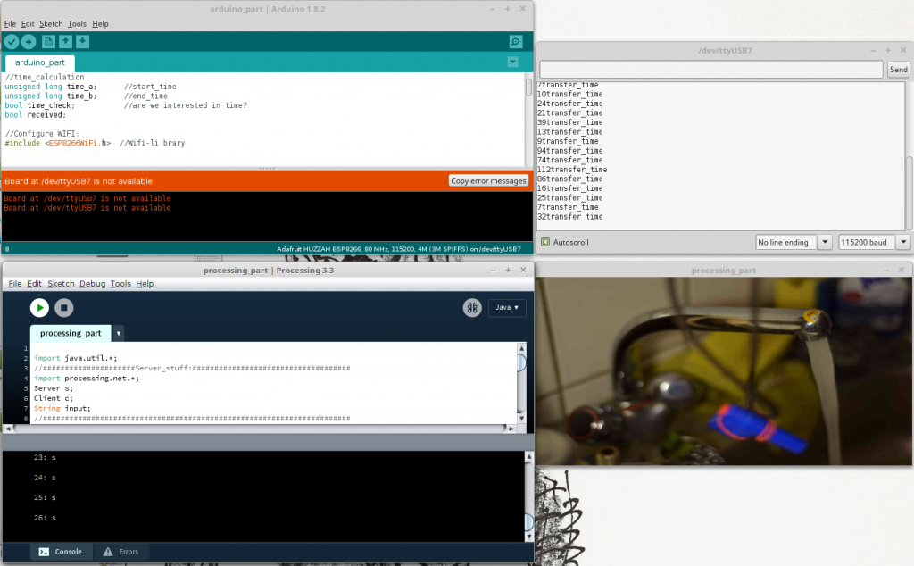
In this so called „Tutorial“, I will document my research and steps to establish a real-time server-client-communication(raw data) between the Feather as a WIFI Client and a simple Processing Sketch as a Server. The Feather collects Sensor Data(button press), sends it wireless to the processing server. The Server(Processing Sketch) changes its status and sends feedback to the Feather, which lights a LED after a successful communication.
The research was kind of difficult. There are some tutorials, but unfortunately no real-time communication tutorials. Due to the fact, that I am new to Web-technology, my solution might be a bit unconventional? (You might leave a comment if that is the case). Anyway here is my solution.
01-Step-by-Step-Tutorial:
I used the following components:
BASIC-Hardware
Adafruit Feather HUZZAH ESP8266
A Network(WLAN-Router, WIFI)
A Computer
BASIC-Software:
Arduino IDE
Processing
a)At first, you should set up everything:
Here, we can stick to Adafruit’s Tutorial, it is very detailed. Here are the steps in short:
Now everything should be configured and you might want to check a simple sketch(LED Blink?) and a simple WIFI-Connection? At this point we have to build our own application, without the Adafruit-Server, to get the freedom of our own server.
b) Set-Up the Arduino-Client
I use a simple Button-circuit as a sensor.(Button=1 if pressed) And I can control a LED: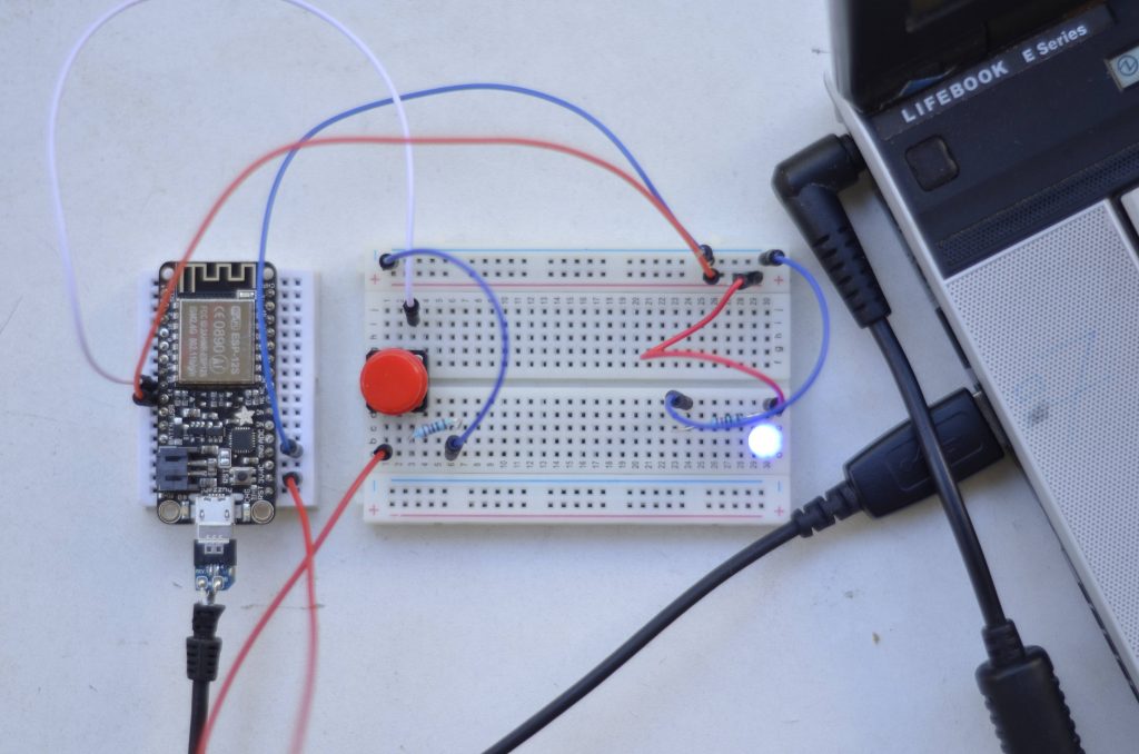
You can use any other sensor instead of a button and any other actuator instead of a LED.
My final code will look like this:
CODE-Arduino
//programm_specific
#include <string> //to use string
int pin_out_LED; //LED
int pin_in_BUTTON; //Button
int pressing; //remembers if button is pressed
int counter; //message_out counter
String msg; //message_out content
String line; //message_in content

//time_calculation
unsigned long time_a; //start_time
unsigned long time_b; //end_time
bool time_check; //are we interested in time?
bool received;

//Configure WIFI:
#include <ESP8266WiFi.h> //Wifi-li brary


//WLAN-Config
const char* ssid = "YOUR_WIFI_NAME_?"; //Your WIFI Name?
const char* password = "YOUR_WIFI_PASSWORD?"; //Your WIFI Password?

//Host&Client
WiFiClient client; //Feather as a client
const char* host = "192.168....IP_AD.."; //My Server(processing) IP Address(Terminal:"ifconfig -a")
const int httpPort = 12345; //Servers port


void setup() {

 Serial.begin(115200); //baud rate
 pin_out_LED = 14;
 pin_in_BUTTON = 12;
 pressing = 0;
 counter = 0;
 time_a = millis();
 time_b = millis();
 time_check = false;
 received = false;
 pinMode(pin_out_LED, OUTPUT);
 pinMode(pin_in_BUTTON, INPUT);

 // We start by connecting to a WiFi network
 Serial.println();
 Serial.print("Connecting to ");
 Serial.println(ssid);

 WiFi.begin(ssid, password); //Connect to WIFI
 digitalWrite(pin_out_LED, HIGH);
 while (WiFi.status() != WL_CONNECTED) {

 delay(500);
 Serial.print(".");
 }
 digitalWrite(pin_out_LED, LOW); //We are connected to SSID
 Serial.println("");
 Serial.println("WiFi connected");
 Serial.println("IP address: ");
 Serial.println(WiFi.localIP());
}

void loop() {

 if (!client.connected())
 {
 if (!client.connect(host, httpPort))
 {
 Serial.println("connection failed");
 delay(500);
 }
 } else {
 //Read Sensor
 if (digitalRead(pin_in_BUTTON)) //if( 1==digitalRead(..)) Button pressed?
 {
 if (pressing == 0)
 {
 counter++;
 if (counter > 100)
 {
 counter = 0;
 }

 msg = String(counter) + ": s \n\r";
 client.print(msg); //SEND to Server

 pressing = 1;
 time_check = true;
 received = false;
 }
 } else {
 pressing = 0;
 }

 while (client.available())
 {
 //READ SERVVVVVVVVVVVVVER
 line = client.readStringUntil('\r'); //READ from Server
 if (line.endsWith("1"))
 {
 digitalWrite(pin_out_LED, HIGH);
 received = true;
 } else if (line.endsWith("0"))
 {
 digitalWrite(pin_out_LED, LOW);
 received = true;
 }
 }

 //To calculate Send_Time
 if (time_check)
 {
 if (received)
 {
 time_b = millis();
 msg = String(time_b - time_a) + "transfer_time";
 Serial.println(msg);
 time_check = false;
 received = false;
 }
 }else
 {
 time_a = millis();
 }
 }

}
1.Include, Declare,..
At first, I declare program-specific variables. To control the LED, I declare „pin_out_LED„, in setup I will set it to 14. To use the Button, i declare „pin_in_BUTTON„, in setup I well set it to 12, because of my feather-circuit. Additional I have to set the pin Modes: „pinMode(pin_out_LED, OUTPUT)“ and „pinMode(pin_in_BUTTON, INPUT)„. To remember whether the the button is pressed, I use „pressing„. A „counter“ counts the messages send by the feather. I use „msg“ and „line“ to send and read messages.
Furthermore I want to check the message-transmission-time with „time_a„, „time_b“ and „time_check„. Later more about this.
Now we have to get the WIFI working. In a) point 4, you should have installed the ESP8266, now we want to include it to our code(„#include <ESP8266WiFi.h>“) to make use of it. Manipulate the ssid by entering your WIFI’s name: const char* ssid = „YOUR_SSID_NAME_?“ and do the same with the password: const char* password = „YOUR_PASSWORD_?„. This will work for a simple WIFI connection, not with a special network, for example the university’s eduroam, where you need a username and password. For further information check here( Jan 07, 2017). For me, a cheap router or my smartphone’s LAN worked fine.. We have to make the Feather as a client: „WiFiClient client“ . You need to know and enter your hosts IP-Address(const char* host = „192.168.1.33“) You need to check it at the computer, where your server(processing sketch) runs. A short research will help to find it. In Ubuntu/Linux, one can simply enter „ifconfig -a“ in Terminal to get it. Later in the processing sketch, we will define a port, through which we will communicate to the server. You can use this one(const int httpPort = 12345).
2.setup()
The setup() part is pretty much straight forward. We begin connecting to the WIFI and the LED is High and we print dots in the Arduino-IDE-Serial-Monitor(Ubuntu: STR+Shift+M), while it is connecting.
It should print: „Wifi connected“.
3.loop()
We always check, whether we are already or still connected to the server. „if (!client.connected())“ . There is a great difference towards the next if request: „if (!client.connect(host, httpPort))“ In contrast to the first, the second one always sends a new server connection request! We only need a new connection if we are not connected yet! Usually Client-Server communication uses client.connect(host, httpPort). A client sends a request and closes the connection, but we do not want to close the connection. We stay connected to save time! We don’t use the common HTTP Get Request, we will simply send RAW-Sensor-Data. That should be efficient and therefore better for real-time communication! At first I was not aware of the difference, I was only using the second one. After sending about 500 messages between server and client I received „exception 29″ in the Arduino Serial-Monitor, because of memory overflow. Furthermore processing warned „client got end-of-stream„.
Anyway if we can not connect to the host-server(processing) it will print connection failed. If we are already connected, the procedure can go on!
We only want to send a message, if(if (digitalRead(pin_in_BUTTON))) the Button is newly(if (pressing == 0)) pressed(I press once and hold it pressed, but I only want to send one message!) Whenever that is the case, we send a message(and make counter++, make a time_check,..):
msg = String(counter) + „: s \n\r“;
client.print(msg);
I will always send and receive with a \r at the end of the message, to make it easier to parse! To receive a message, we check whether there is an incoming message with client.available().
line = client.readStringUntil(‚\r‘);
We read the message until ‚\r‘ and check, whether we received a „1“ or „0“ and according to this, we turn the LED HIGH or LOW.
In between, there is some time_checking. You might want to use or improve it? I get 4ms to 100ms transmission time and in average about 15ms.
c)Set Up the Processing-Server
Now I create a simple server on my computer, using processing .I want to receive a message sent by the feather/client to trigger(on and off) a virtual water faucet(older project of mine):
Whenever there is a change, I want to send feedback to the feather/client(feather lights the LED).
My Full-Code will look like this:
CODE-Processing
import java.util.*;
//#####################Server_stuff:####################################
import processing.net.*;
Server s;
Client c;
String input;
//######################################################################

//Bilder:
ArrayList<PImage> bilder_a;
ArrayList<PImage> bilder_b;

int phase; //Aktuelle Bild-Nr
int direc; //An oder Aus?
int mode; //Focus
int pic_anzahl; //Anzahl an Bildern

void setup() {
 //Video:
 //fullScreen();
 size(600, 300);
 frameRate(25);
 orientation(LANDSCAPE); //Bug?!

 //Load Pictures:
 bilder_a=new ArrayList();
 bilder_b=new ArrayList();
 pic_anzahl=9;

 String pic_name;
 for (int i=0; i<=pic_anzahl; i++)
 {
 pic_name="pic_a"+i+".JPG";
 bilder_a.add(loadImage(pic_name));
 pic_name="pic_b"+i+".JPG";
 bilder_b.add(loadImage(pic_name));
 }

 //Setting_UP:
 phase=0; //Wasser Bild 0
 mode=0; //Focus auf Hebel
 direc=-1; //Wasser auschalten

 //#####################Server_stuff:####################################
 s = new Server(this, 12345); // Start a simple server on a port
 //######################################################################
}

void draw() {
 //#####################Server_stuff:####################################
 c = s.available();
 //println(c);
 if (c != null)
 {
 input = c.readStringUntil('\r');
 //input = input.substring(0, input.indexOf("\n")); // Only up to the newline
 println(input);

 if (input.contains("s"))
 {
 if (phase==0)
 {
 phase=1;
 //#####################Server_stuff:####################################
 s.write("1\r");
 } else {
 s.write("0\r");
 //######################################################################
 }
 direc=direc*-1;
 }
 }

 //######################################################################

 if (phase>0) //Wasser läuft
 {
 if (phase>8) //Repeat:
 {
 phase=4;
 }
 phase+=direc; //Up or Down
 }

 //Focus:
 if (mode==0)
 {
 image(bilder_a.get(phase), 0, 0, width, height); //Focus: Hebel
 } else
 {
 image(bilder_b.get(phase), 0, 0, width, height); //Focus: Hahn
 }
}

void mousePressed()
{
 if (mouseX>width/2) //switch foucs: Hebel/Hahn
 {
 mode++;
 mode=mode%2;
 } else //switch Wasser: an/aus
 {

 if (phase==0)
 {
 phase=1;
 //#####################Server_stuff:####################################
 s.write("1\r");
 } else {
 s.write("0\r");
 //######################################################################
 }
 direc=direc*-1;
 }
}
To make the faucet working, you need the whole project with pictures, here.
1.Include, Declare,..
I import processing.net.* to be able to use Server and Client!
2.setup()
I open a Server s = new Server(this, 12345); at port 12345. You can change the port if you like.
3.draw()
To receive a message send by feather/client, we check whether there is an incoming message with c = s.available().
If there is a message( if (c != null)), we read the incoming String until ‚\r‘:
input = c.readStringUntil(‚\r‘);
We check the input, whether it contains(„s“) and change the faucet’s state and transmit the changes back to the feather/client:
s.write(„1\r“);
The rest of the Code contains only my faucet mechanics.
I hope my tutorial helps people getting their real-time feather to processing application working!
02-Some Ideas:
a)Just to answer some study-questions:
b)Just to give some study-questions:
c)Further Ideas: