
Introduction: The nRF24L01 is a single chip radio module. Our task was to get two nRF24L01 up and running, connecting both and transmitting flex-sensor data. For this our hardware was:
- 2x nRF24L10
- 2x Atmega nano v3
- 1x Flex sensor
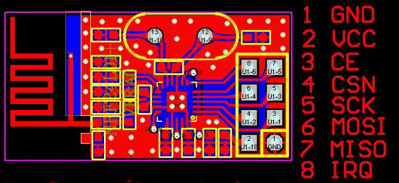
Step-by-Step: Our first step was trying to understand the pins on the nRF24L01. It has 8 pins in total: GND/VSS (Ground), VCC (power supply), CE (digital input RX/TX), CSN (digital Input SPI chip select), SCK (digital SPI clock), MOSI (digital SPI slave data input), MISO (digital SPI slave data output), IRQ (digital maskable interrupt pin).
First find: It ueses the Serial Peripheral Interface (short SPI), hence we need to look up what the default SPI pins on an Arduino are. Pin 10 (SS ), Pin 11 (MOSI), Pin 12 (MISO), Pin 13 (SCK).
With that info. we can hook up our Arduino and the nrf24L01 since we now only need to match our ports.
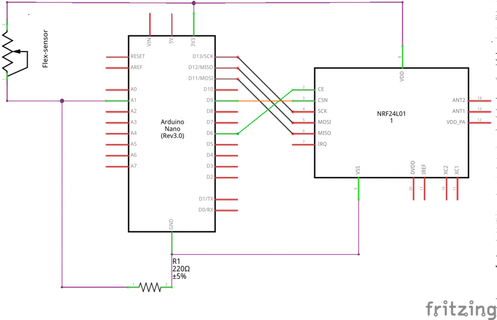
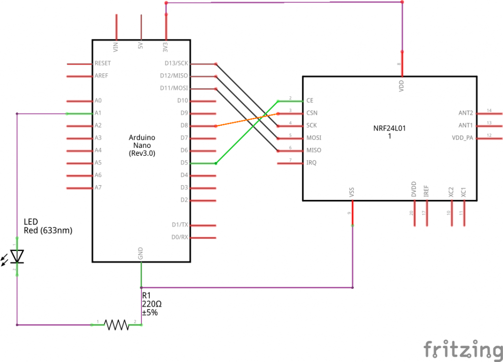
We modified the simple sketch by adding in a sensor on one side and an LED on the other. Now the only thing left to do for the initial task would be connecting both nRF24L01. For this we worked in the Arduino IDE.
// SENDER CODE:
#include <RF24.h>
#include <nRF24L01.h>
#include <RF24_config.h>
#include <SPI.h>

RF24 radio(6,9);
int data[1];

void setup(void){
  Serial.begin(9600);
  pinMode(A1, INPUT);

  radio.begin();
  radio.enableDynamicPayloads();
  radio.setPALevel(RF24_PA_MAX);
  radio.setChannel(1);
  radio.openWritingPipe(0xF0F0F0F0E1LL);
}

void loop(void){
  data[0] = analogRead(A1);
  radio.write(&data, sizeof(data));
  Serial.print("Sent: ");
  Serial.println(data[0]);
}
// RESIEVER CODE:
#include <RF24.h>
#include <nRF24L01.h>
#include <RF24_config.h>
#include <SPI.h>

RF24 radio(5,8);
int data[1];

void setup(void){
  Serial.begin(9600);
  pinMode(A1, OUTPUT);

  radio.begin();
  radio.enableDynamicPayloads();
  radio.setPALevel(RF24_PA_MAX);
  radio.setChannel(1);
  radio.openReadingPipe(1,0xF0F0F0F0E1LL);
  radio.startListening();

}

void loop(void){

  if (radio.available()){
    boolean dump = false;
    while (!dump){
      dump = radio.read(&data, radio.getDynamicPayloadSize());
      digitalWrite(A1, HIGH);
      Serial.println(data[0]);
    }
    delay(100);
  }
  else{
    Serial.println("No radio available");
    delay(1000);
  }
}
The first snippet of code is our sensor rig, which sends its sensor-data to the other nRF24L01 that is defined by the second code. For this there is primaraly only one thing to keep in mind. One nRF24L01 sends, the other resieves. If the roles are to be switched one has to specifically stop the old role nad start the new one. Since we did not do this, we just have to focus on the communication. To make it work there are only a couple of steps needed. Both need to communicate on the same Pipe, you need a sender and resiever and you need to know how big the thing is you are trying to send. Done the rest is fancy stuff.