Category Archives: Our costumes
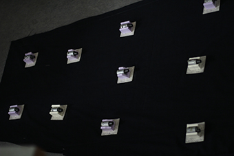
The NEMO costume re-tested.
On 15 August the Rafael Ecker came to HCI lab and Tested the costume once again.
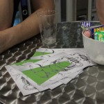
Final Exhibition Summary / Open Lab Night

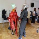
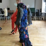
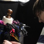
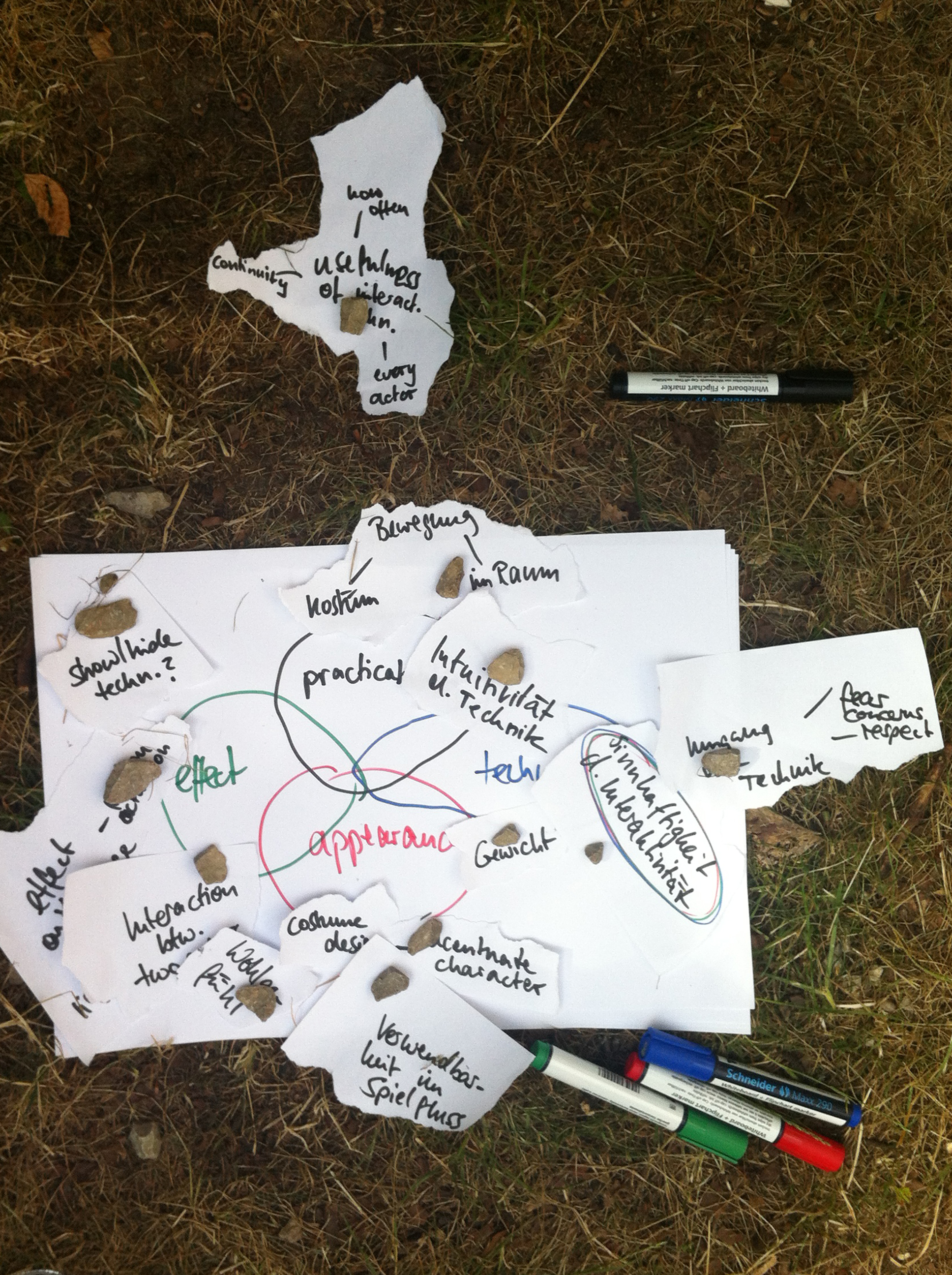
Design Acting – Octopus
Photos from design acting workshop
The actress had fun with the costume
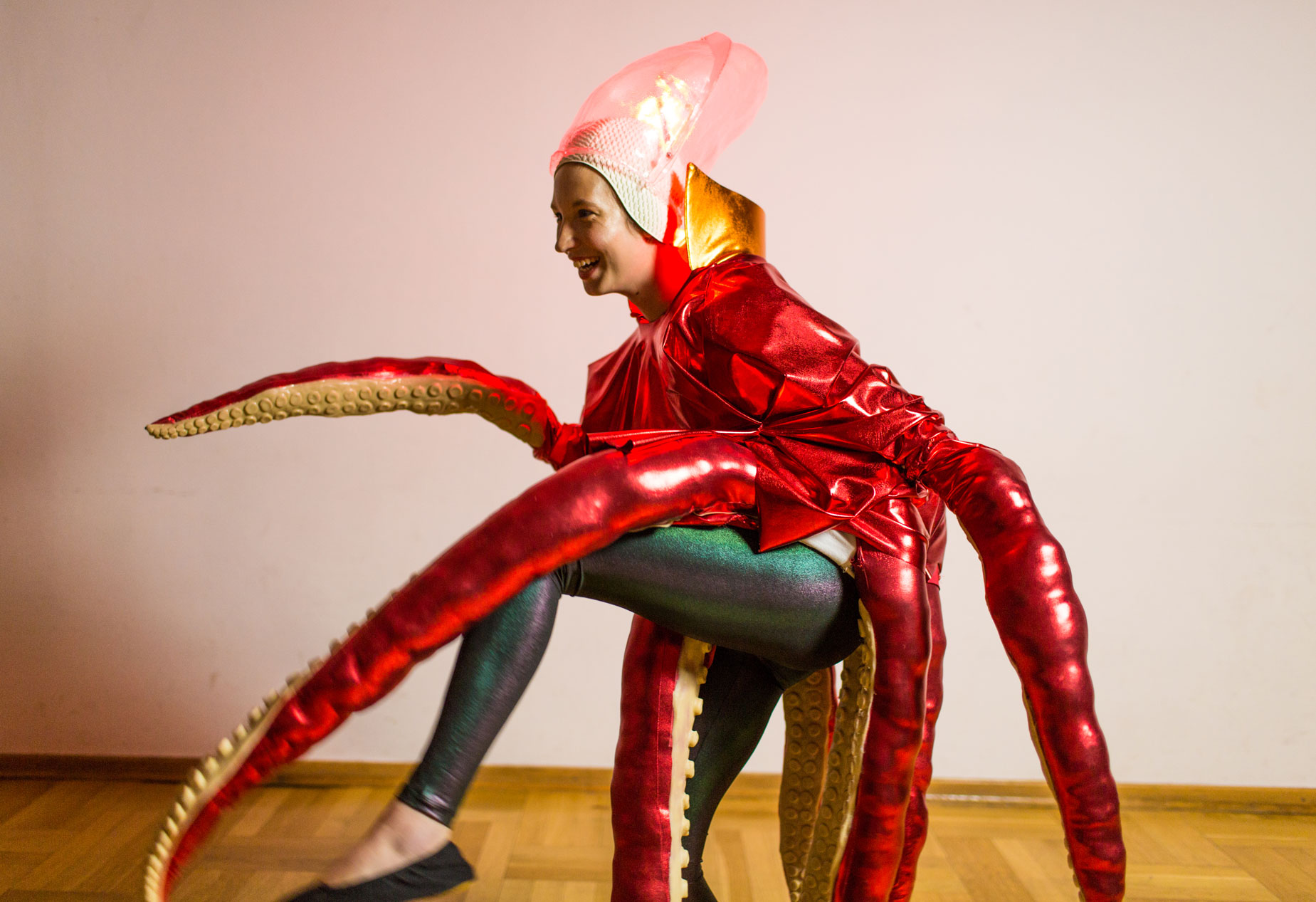
different mood
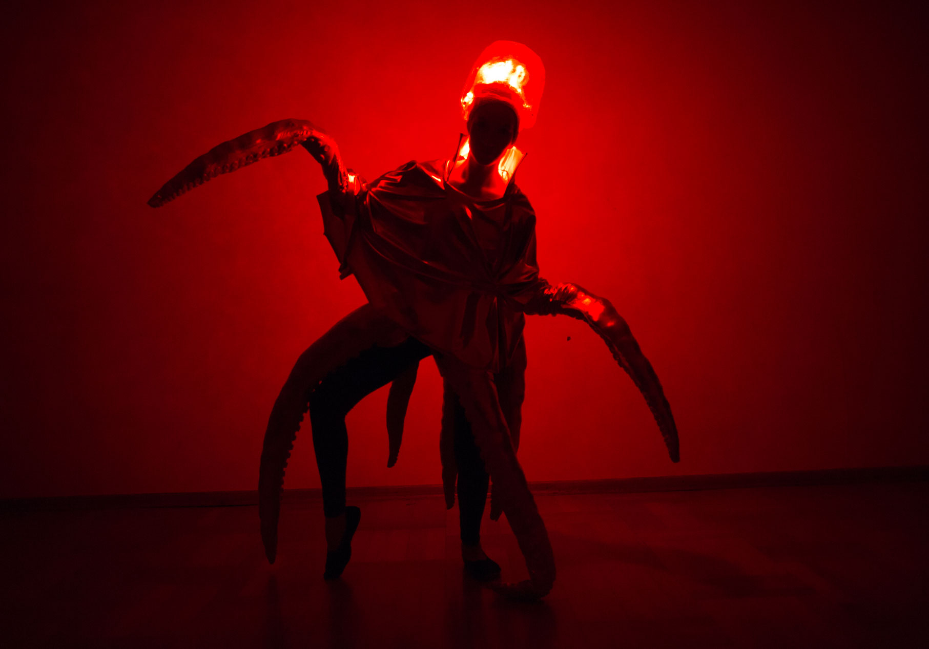
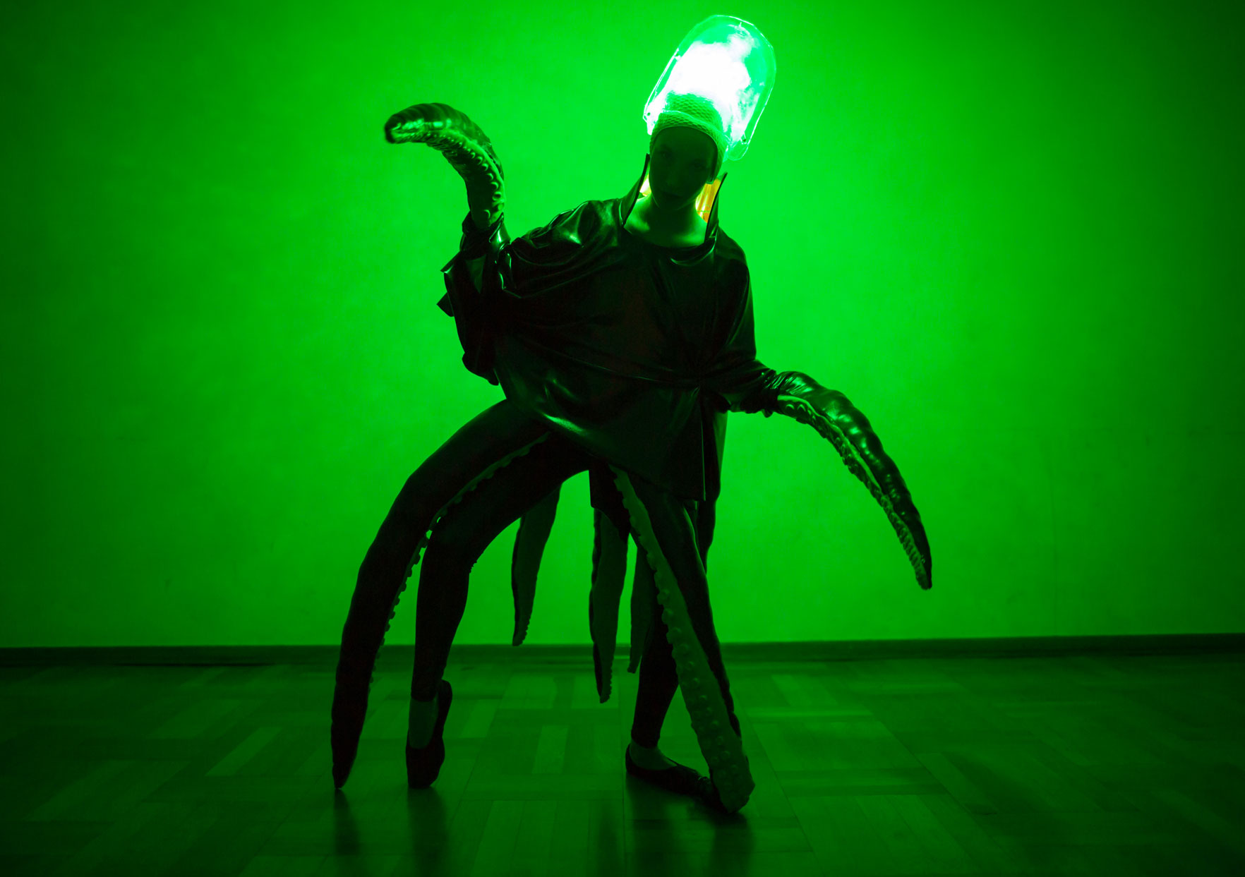
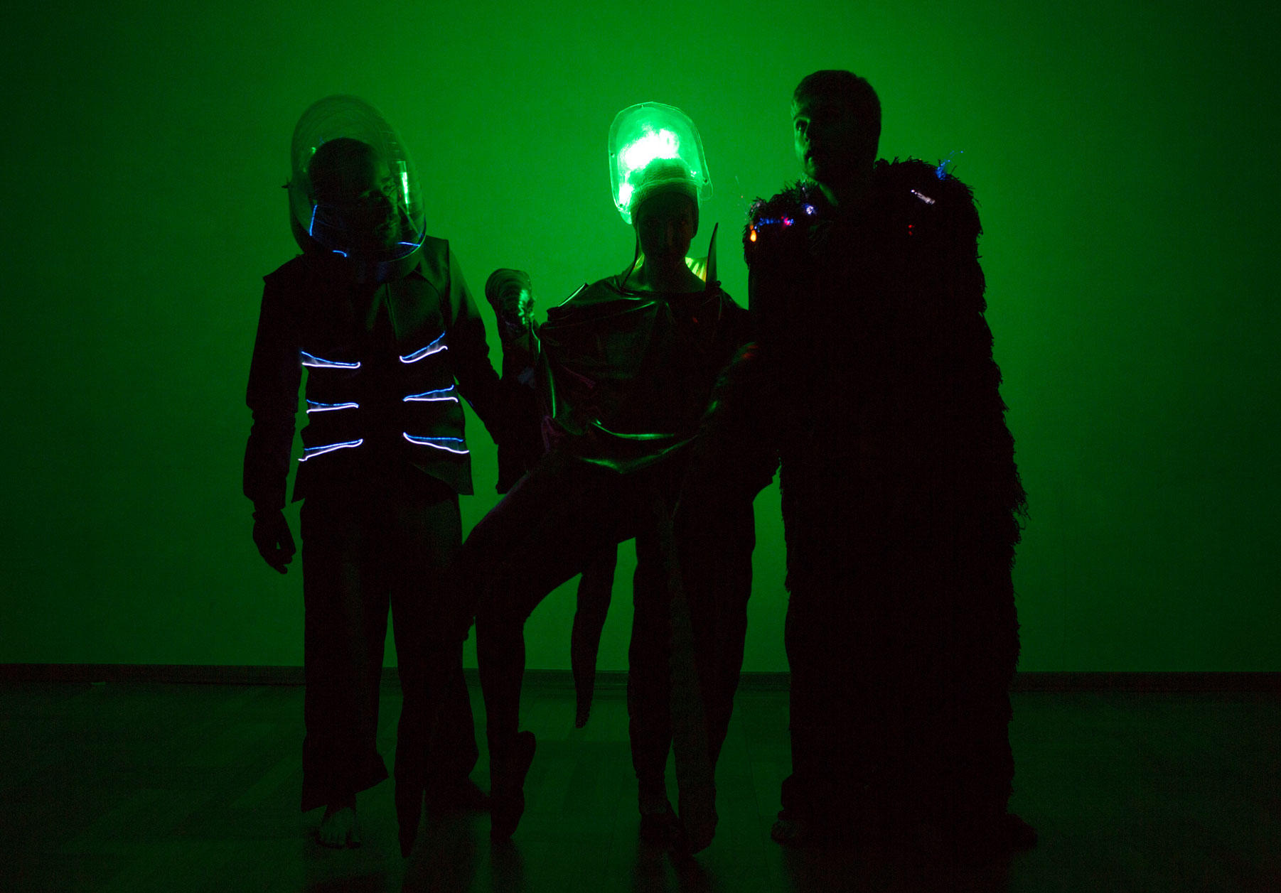
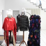
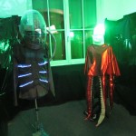
diver, octopus and nemo
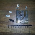
Homemade PCB
For rapid prototyping it is often useful to have circuits on a circuit board instead of a breadboard. In this post I will give a short description of how you can make your own PCB’s in a fast and cheap way with the so called Toner-Transfer Method. This process require some training, so don’t be upset if it doesn’t work the first ten times.
To develop own PCB’s you have six steps to do:
- Preprocessing
- Transfer layout
- Etch
- Postprocessing
- Drill
- Assemble
I consider that you have your schematic and board design finished with the CAD program of your choice. I will use a two-sided layout.
Preprocessing
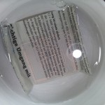
At first export the top and bottom side of your board design as image, and arrange them next to each other. You have to mirror the top layout in order to transfer it in the correct manner onto the PCB later.
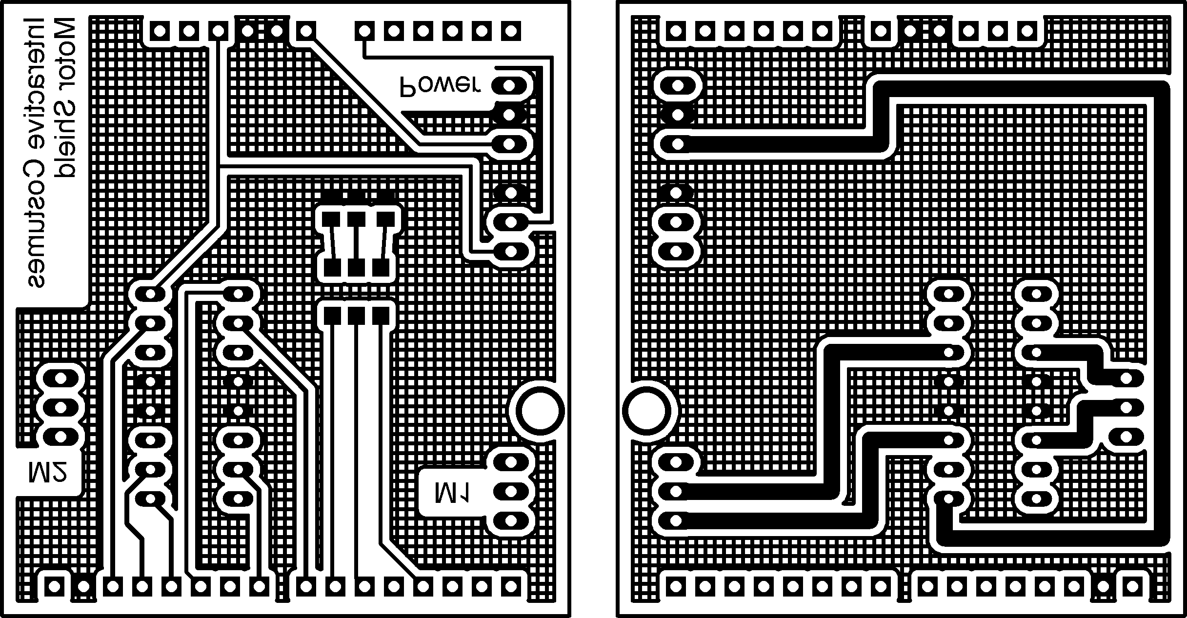
Next you have to print this image with a laser printer on a glossy paper. This prevents the toner from being soaked by the paper completely. It is advisable to print it several times to have some if it doesn’t work the first time.

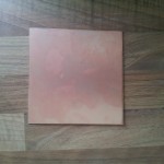
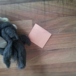
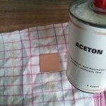
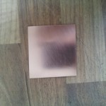
The second preprocessing step is to prepare the circuit board for the transfer. At first cut a piece of circuit board in the dimensions of your layout. Next you have to clean it really good. At first use steel wool for a rough cleaning of the board. After this use acetone to really get rid of all dirt and fat. After this procedure the copper should be shiny like a mirror. During the cleaning and transferring you should wear gloves to ensure the copper stays clean.
Transfer layout
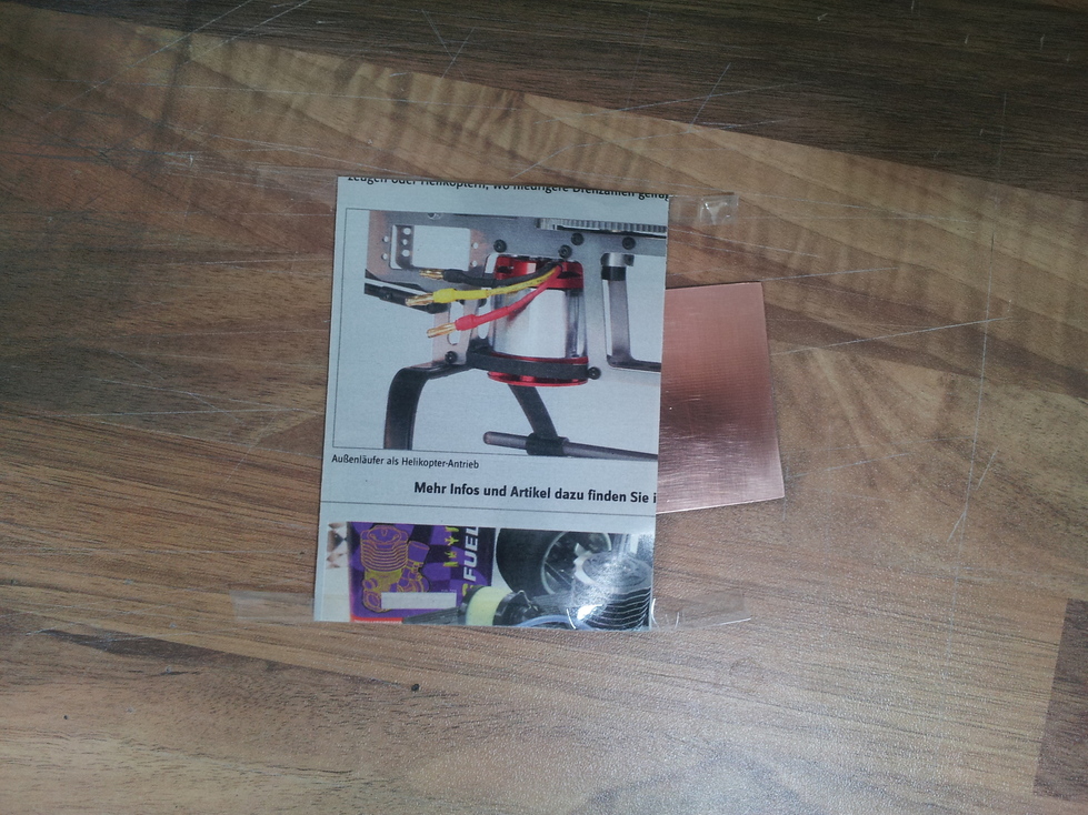
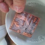
After you have your design on glossy paper and the circuit board is clean, they should come together. Because I have a two-sided layout, I have to ensure that all holes are on the same position for both sides. Therefore, you can build a small bag for the circuit board. Fold the glossy paper with the design so that both sides lie exactly on top of each other. Use duct tape to fix two other sides. Insert your circuit board from the fourth side and place it such that the design borders fit with the circuit board edges.
Now you have to transfer the design onto the circuit board. Therefore, you can use an electric iron. It is advisable to put some cotton rag between the electric iron and the paper. Adjust the electric iron to cotton temperature (This may vary with other electric irons). And start ironing the design.
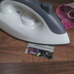
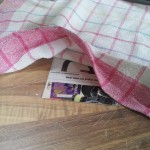
After 5 minutes the toner should be hot enough to stick to the copper. Put the (!HOT!) circuit board in a bowl with cold soap water and wait another 5-10 minutes. Then the catalog paper will dissolve. You can carefully rub over the circuit board to remove the last catalog paper.
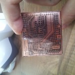
As result, you have a copper board with your design on both sides printed.
Etch
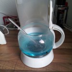
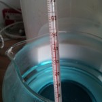
Now comes the interesting part. To etch your layout you need some Sodium Persulfate (NA2S2O8). It should have a temperature around 50°C (not more!). I use the hot plate of an old coffee maker to heat the etchant. Be careful, the etchant will make holes in fabrics, so don’t drip at your clothes (and be careful with your skin as well).
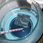
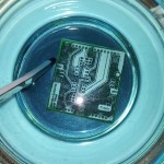
After some minutes you can see how the copper disappears from the circuit board. The toner prevents the design part from being removed by the etchant.
 Next you have to remove the toner. Therefore, you can use again acetone.
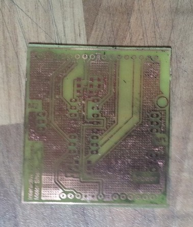
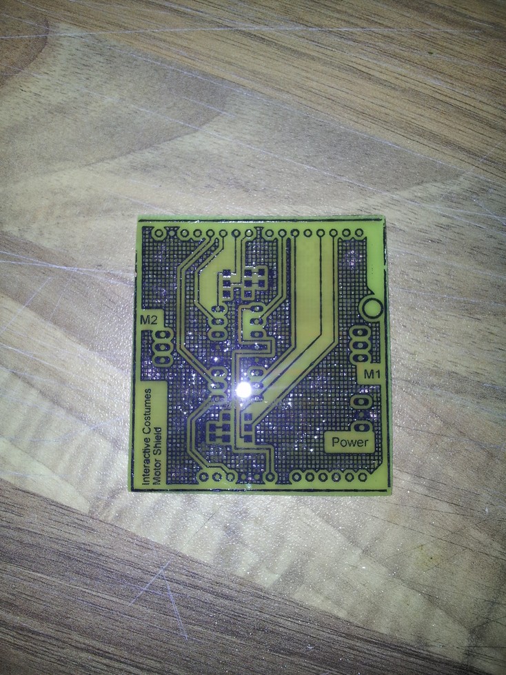
Now your circuit is on the circuit board!
Postprocessing
To prevent the copper from oxidating it is necessary to tin-coat it. For this purpose I use Rosol 3 which is available in the hardware store.
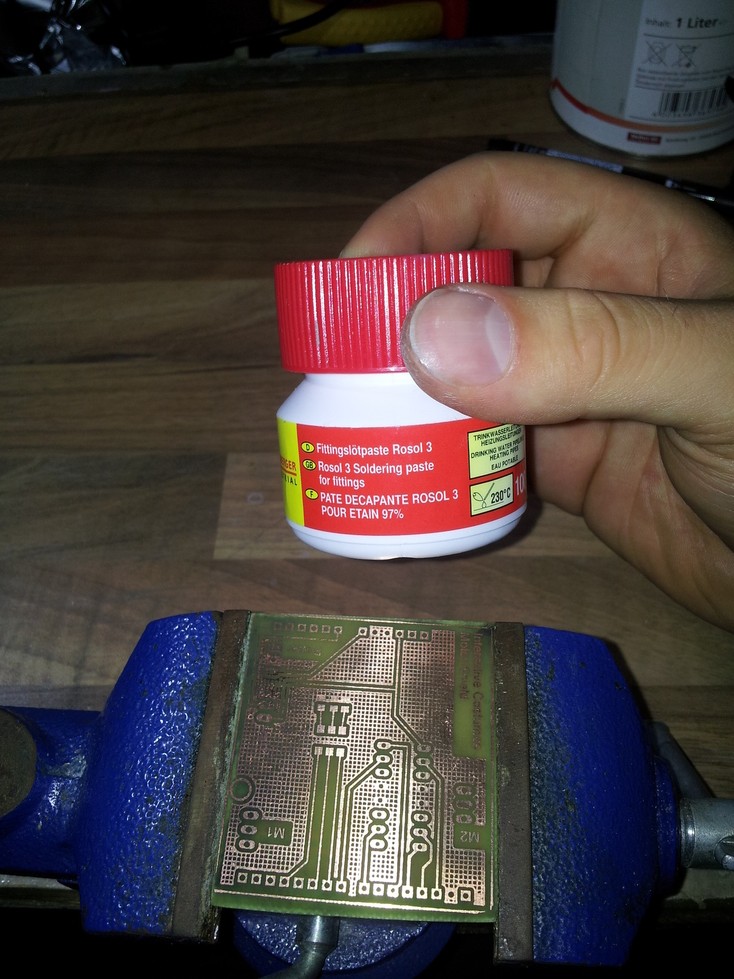
Just brush a thin layer of the Rosol 3 onto the circuit board.
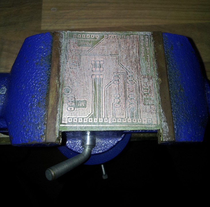
Next use a heat gun to heat the tin until it starts to melt.
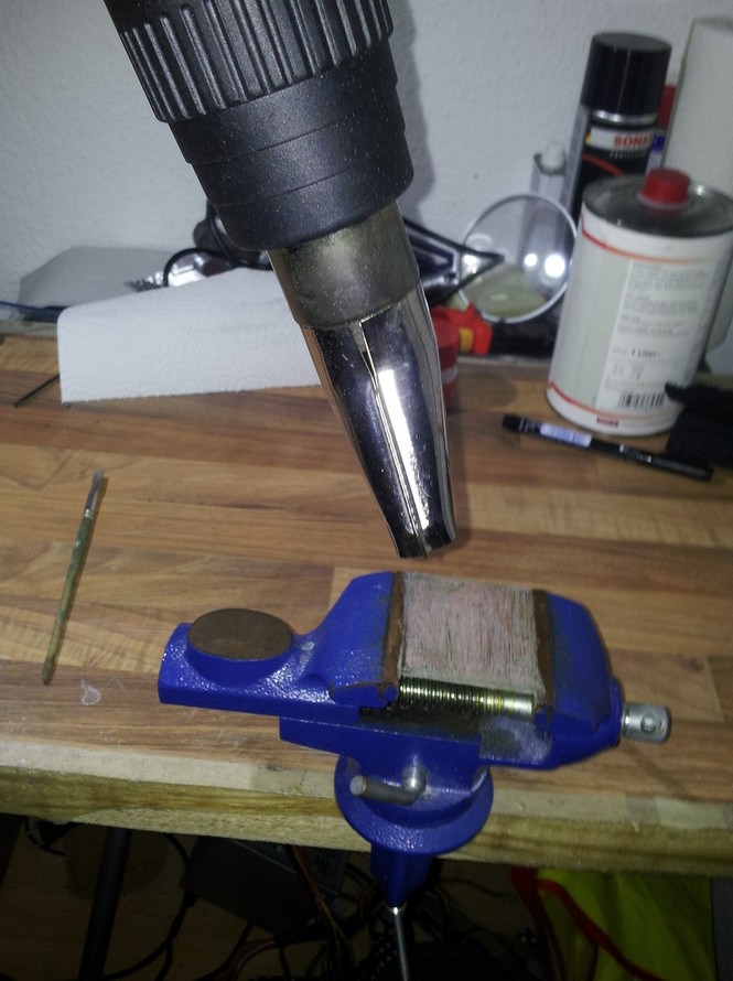
Your circuit board is now silver and protected against oxidation.
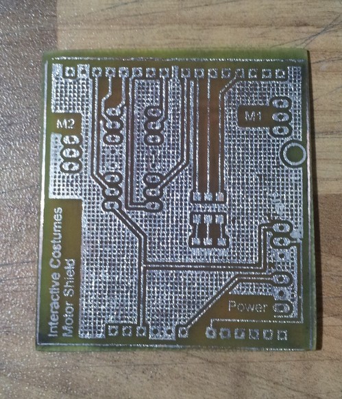
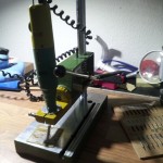
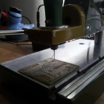
Drill
To assemble the parts to your circuit board you need to drill all the holes. I use a small Proxxon drill with drill rig. Connectors need holes with a diameter of 1.0mm, DIP packages need 0.8mm.
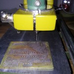
After this step you are nearly finished!

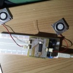
Assemble
Last but not least you have to assemble your parts and test your circuit .
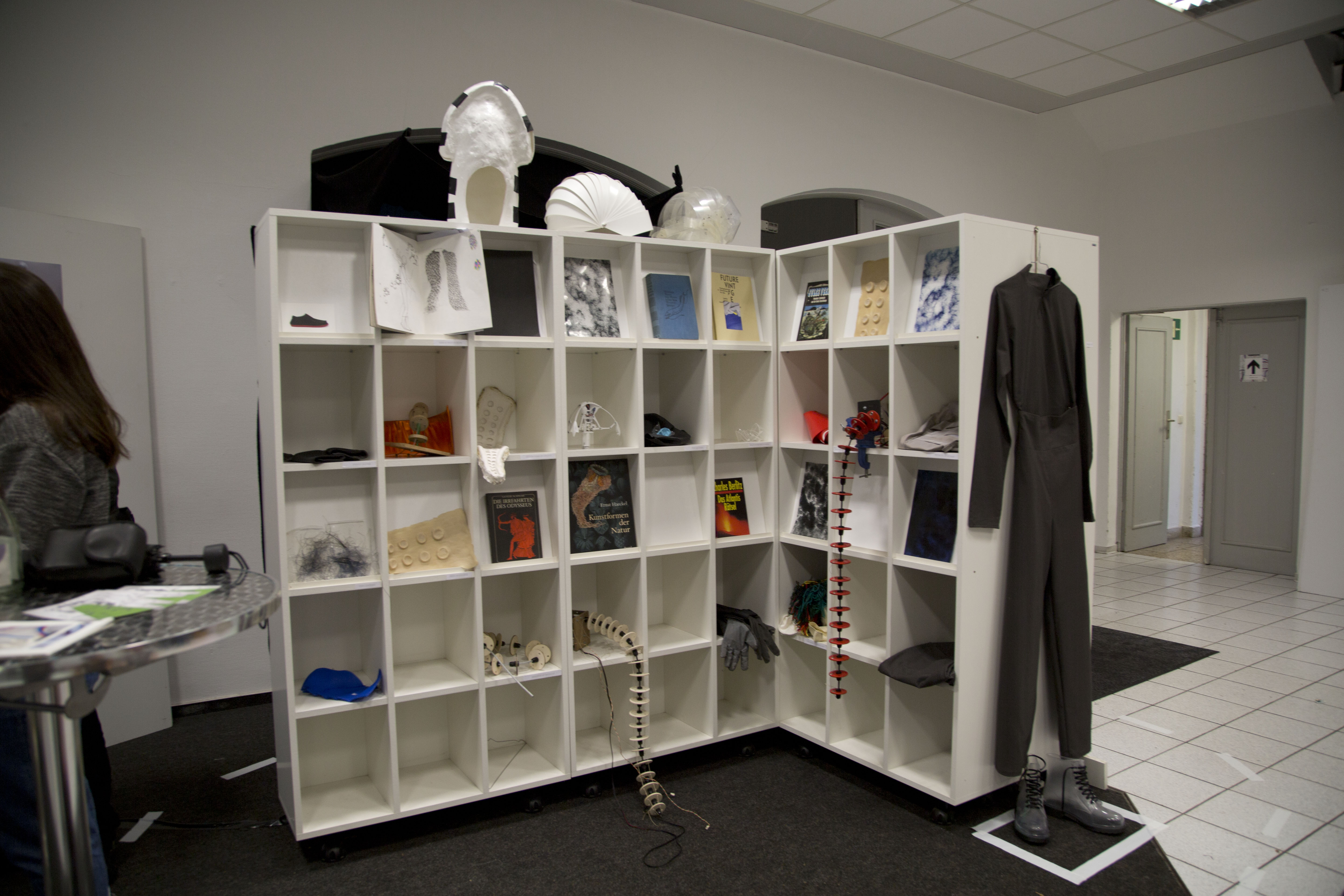
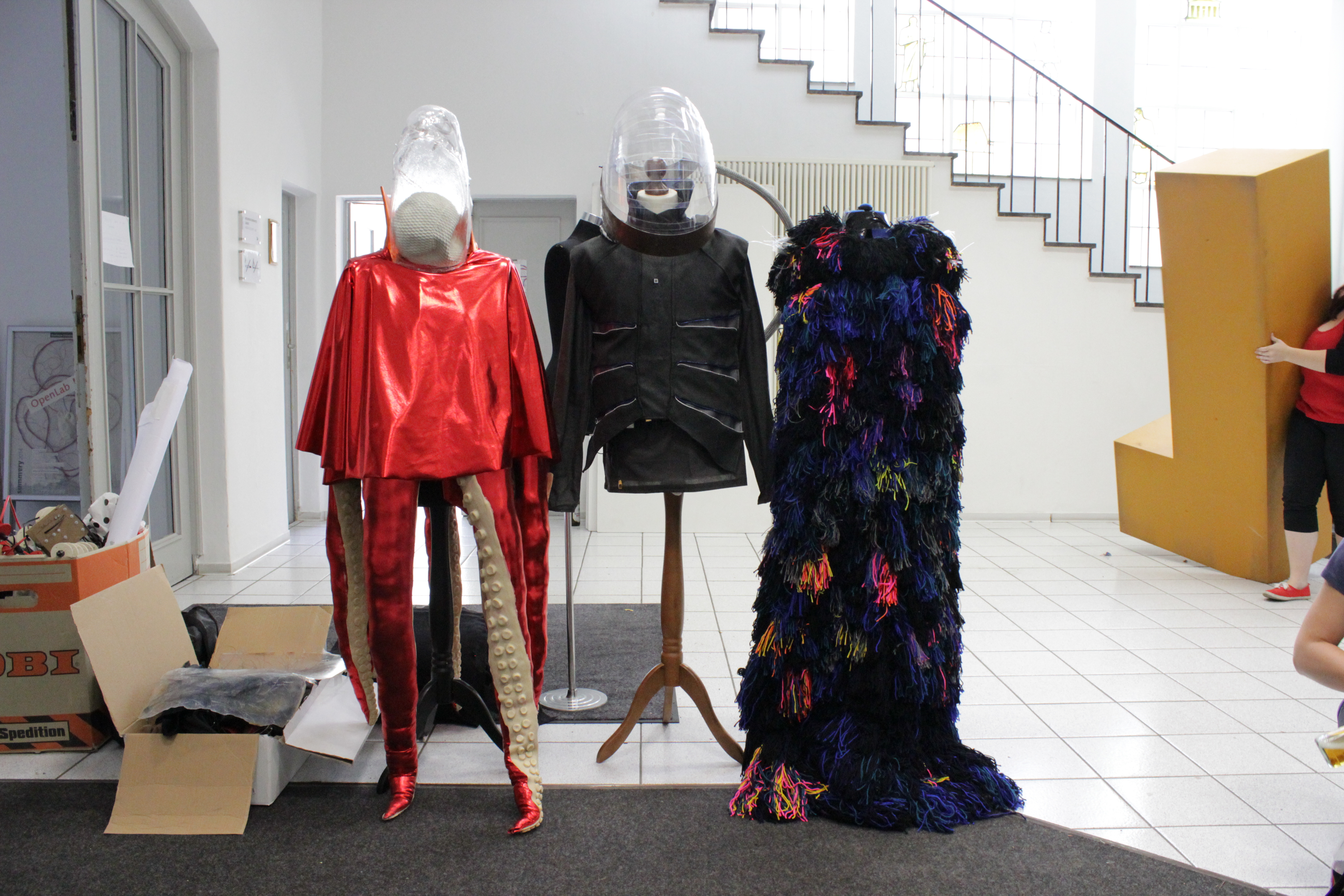
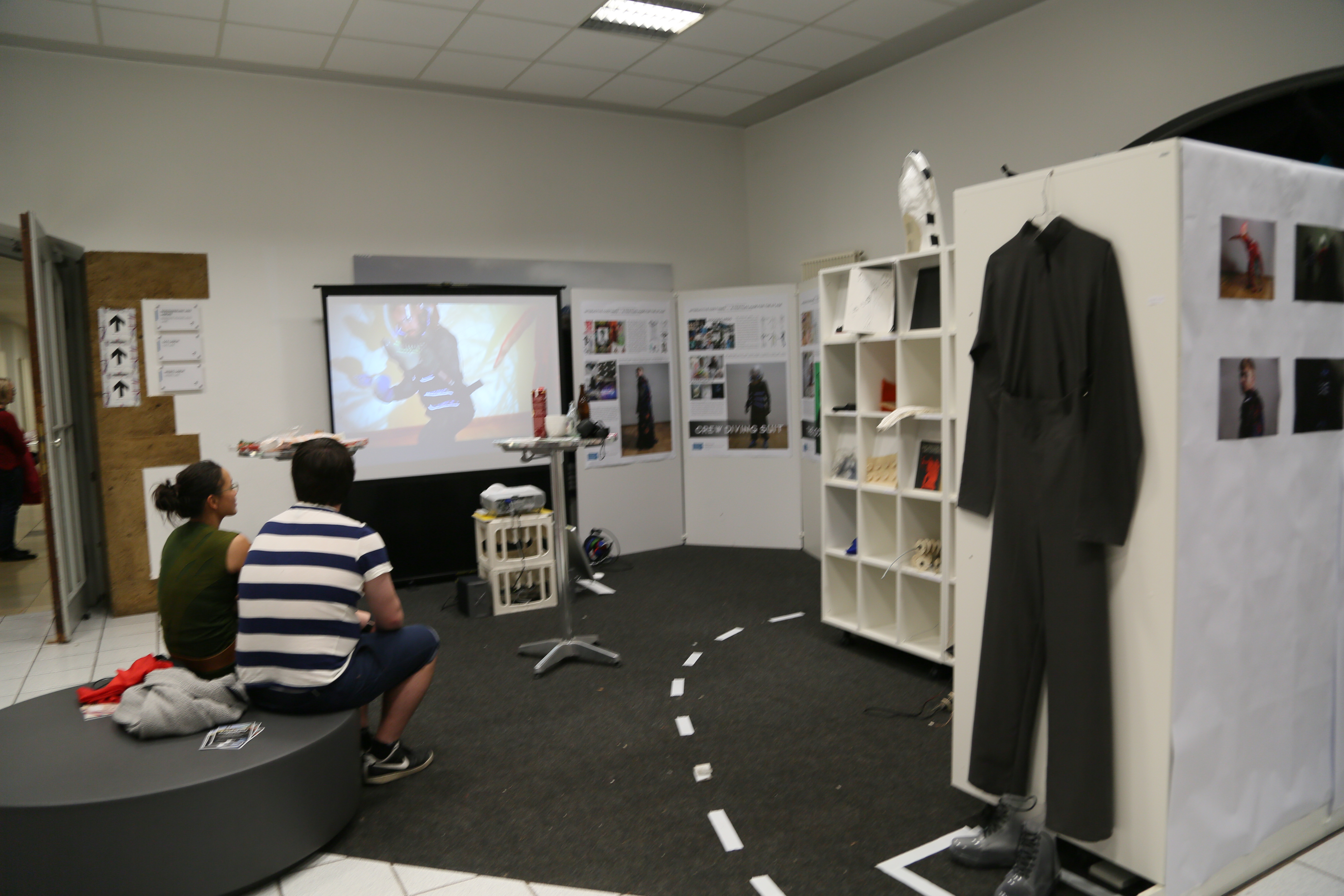
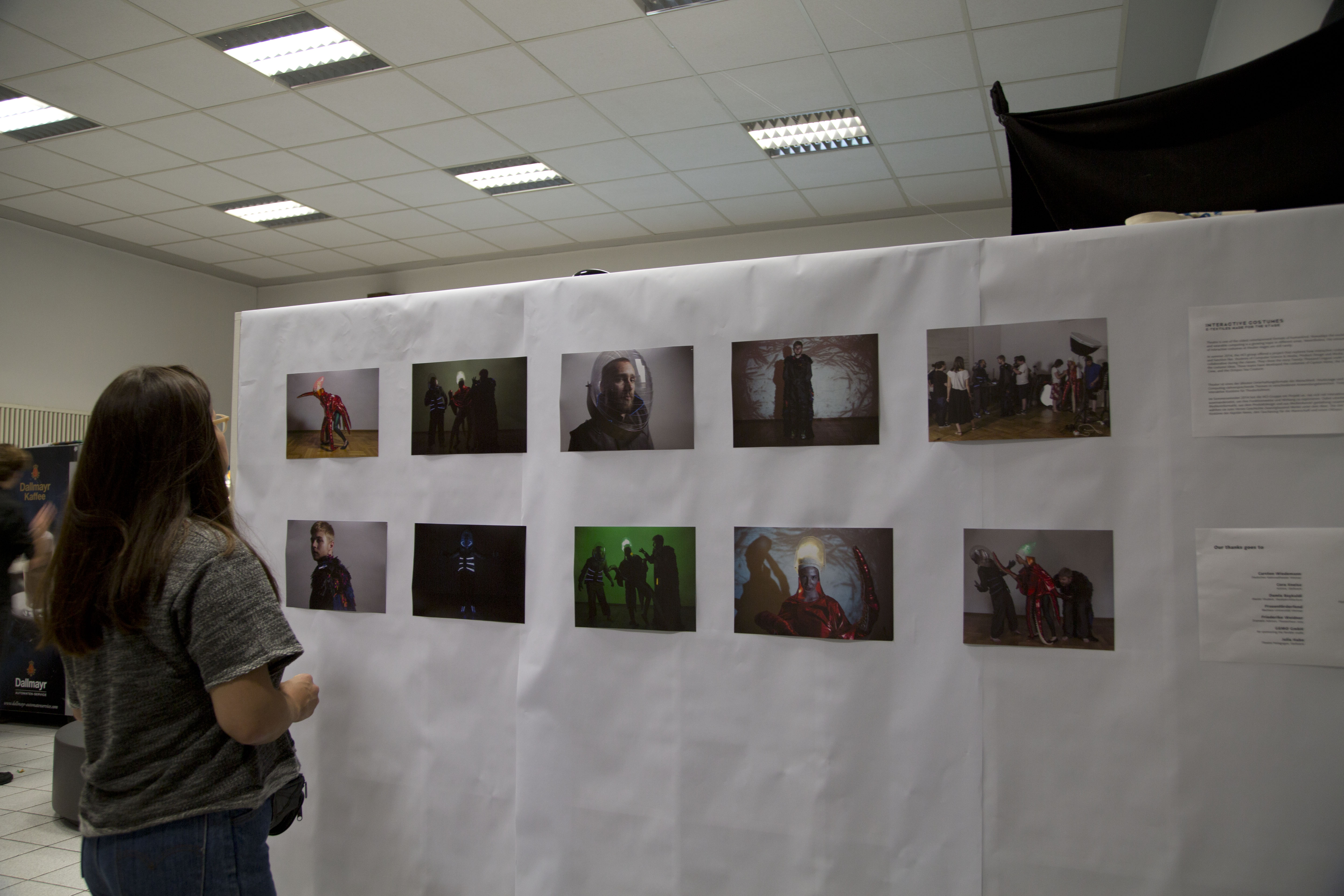
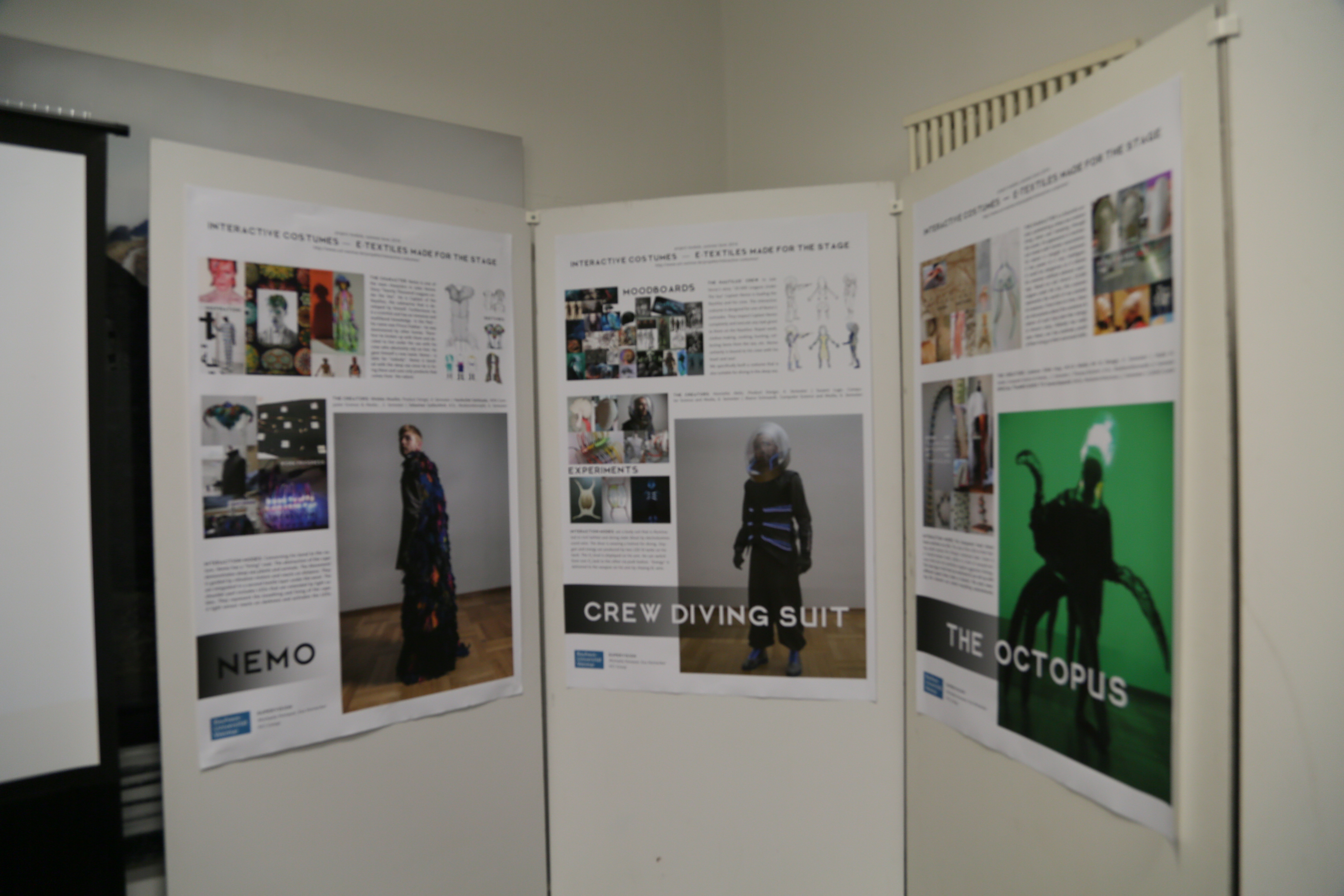
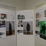
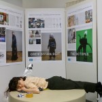
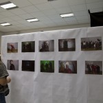
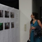
Final Exhibition – Summaery – Open Lab Night
Dear All,
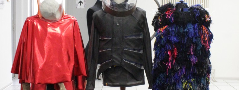
we present to you: our final exhibition!
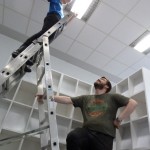
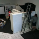
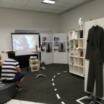
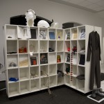
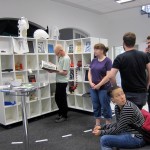
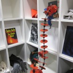
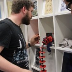
The designers always come up with these crazy ideas that are a lot of effort. I guess in the end it was worth it. We presented the project – costumes, mock- ups, prototypes, pictures and movie in the entrance hall of Bauhausstraße 11. We tried to make it an overall experience so that the visitor understands the project´s goal. The visitor had to pass shelves filled with prototypes and inspirational material. The video that was shot during the design acting weekend gave a perfect introduction to our project´s idea and storyline.
We created a small dark nook to present the costumes with their interactive properties. The visitor really had to enter a “different” world – the Nautilus perhaps?
See here some impressions of set up and opening of our successful exhibition!

Design Acting Workshop

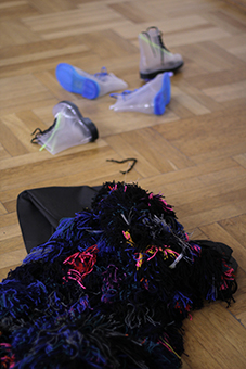
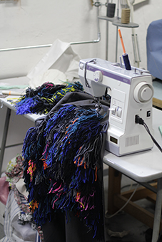
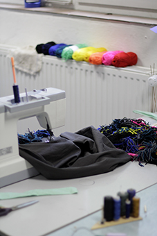
sew the costume (additional pics)
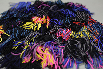
sewing the outside of the cape (wool + cotton textile)
fixation of the motors (2nd layer of the cape): little boxes made of a type of styrofoam, the motors stick into this boxes, finally they’re fixed with cable straps
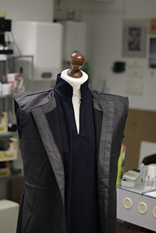
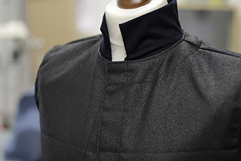
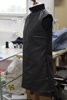
the west (synthetic textile weaving with poly urethan fixation) without the final shoulder part (wool)
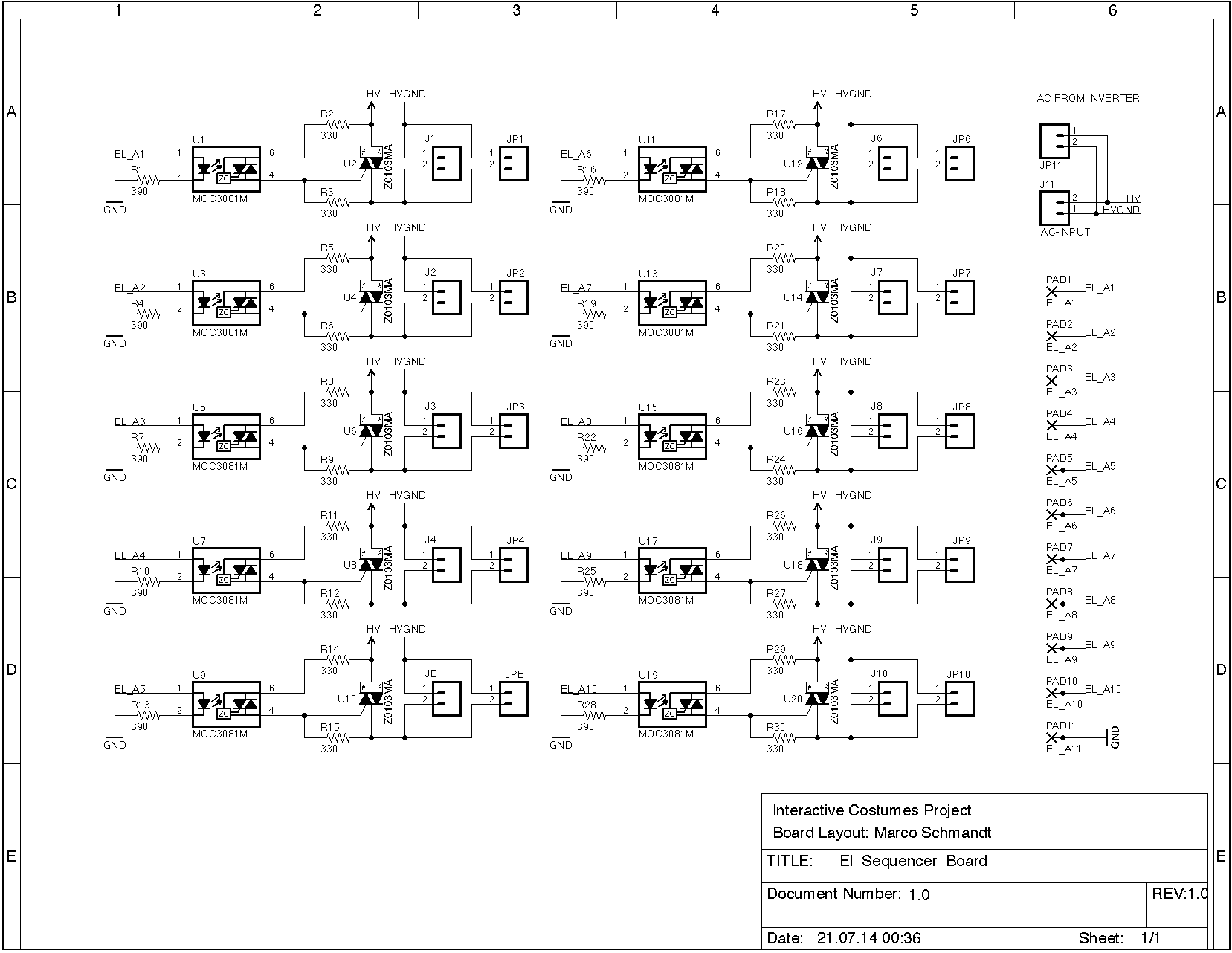
Finished circuit diagram for EL sequencer and a production version in the making
The circuit diagram for our el sequencer board is finished. Now I’m trying to design a version for manufacturing. Meanwhile have a look at the current version of the circuit.
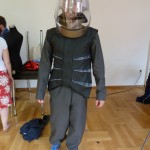
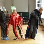
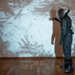
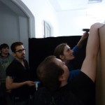
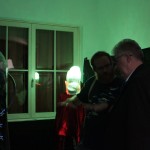
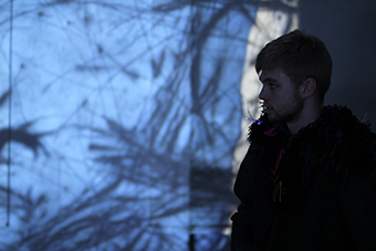
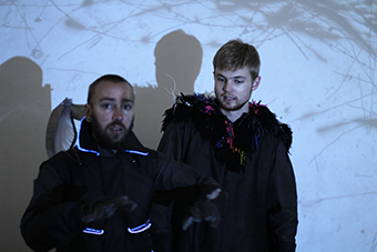
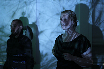
Design Acting – Final Workshop – Diver Costume´s First Time in Action
Our final Design Acting Workshop took place one week before the final grand university exhibition called Summaery!
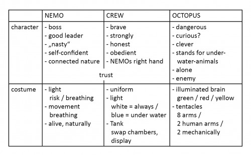
It´s been an exhausting time, since the workshop meant to have the costumes ready to be worn by actual real actors. We only had two days to plan, try out and actually develop and shoot a short performance with all three costumes in action. Friday we spent the day planning the performance/ scene. It meant getting an overview on each character, their presumed “personality traits” and technical features that will enhance those characteristics.
Next step was, to develop a short scene where all characters/ costumes would interact with one another — Where all technical and character traits would also become clear.
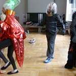
Scene we came up with:
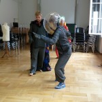
Captain Nemo and his right- hand Crew Member exit the Nautilus for an exploratory mission to the bottom of the sea. While exploring they get too close to the dwelling space of the octopus. They bother him a little too much, so the octopus gets excited and finally angry when the Crew Member tries to attack it. The octopus is stronger and tries to drag the Crew Member aka Diver into his dwelling place. Finally Captain Nemo comes back to rescue his comrade.
We planned to film the entire day with the goal to observe the actors, how the costumes are fit for their character, etc. To get some facts, we developed a catalogue of questions in form of an interview. We have some film footage of interviewing the single actors. Plan is to evaluate and judge our work with the collected information.
We all were really stressed out and nervous on that important day when the actors came in. Really we thought it would be disastrous since none of our costumes was working quite right. We had a lot of technical problems to deal with. In the end though, it worked out fine! The actors fit into the costumes perfectly. Not just size wise, but also character wise. It was so good to see them “using” the costumes in that way.
Here are some impressions: