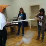
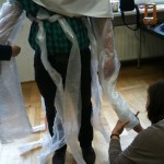
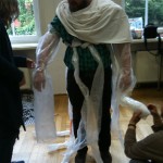
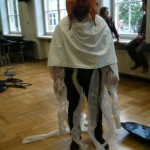
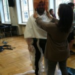
Photos from design acting workshop
The actress had fun with the costume
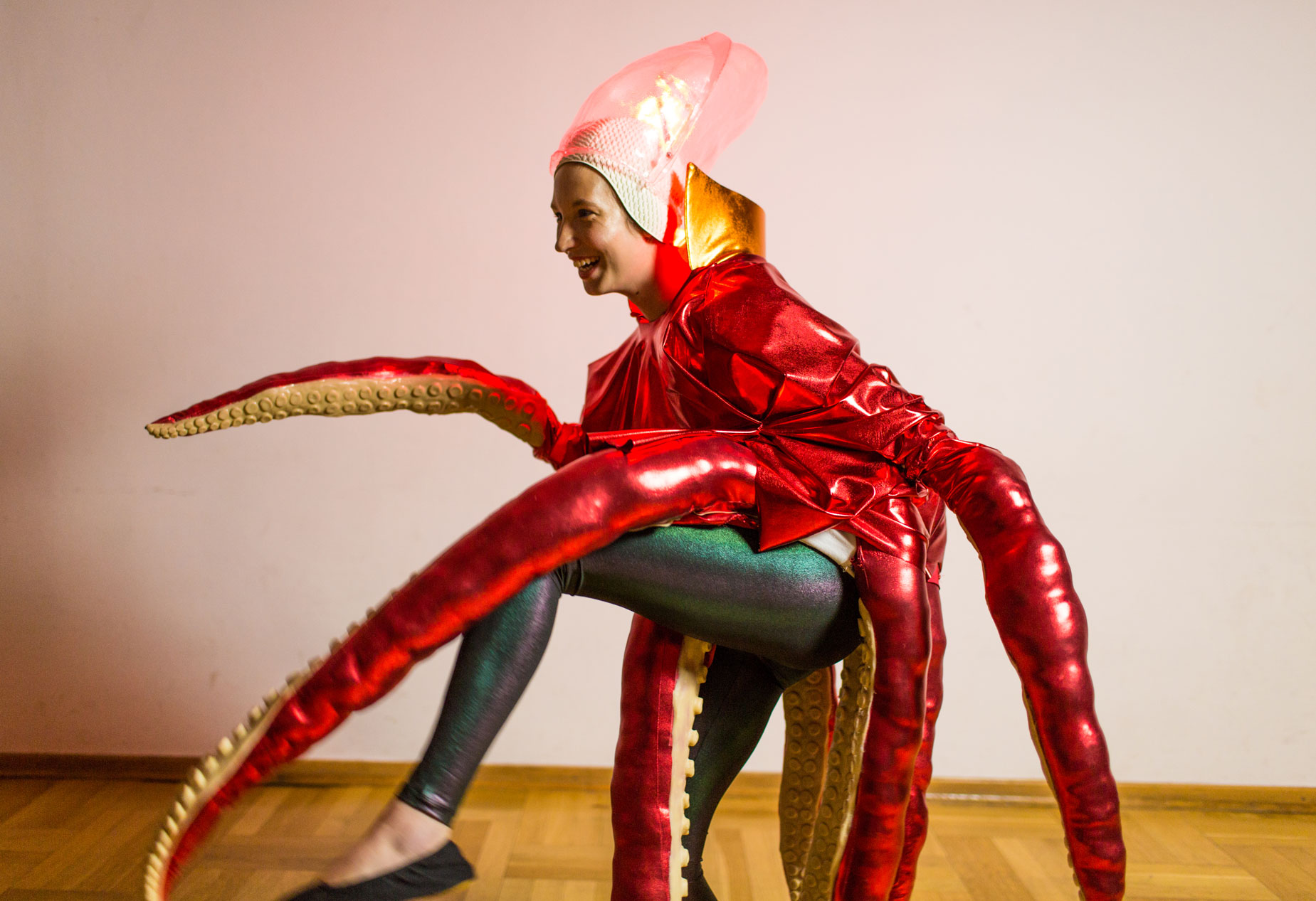
different mood
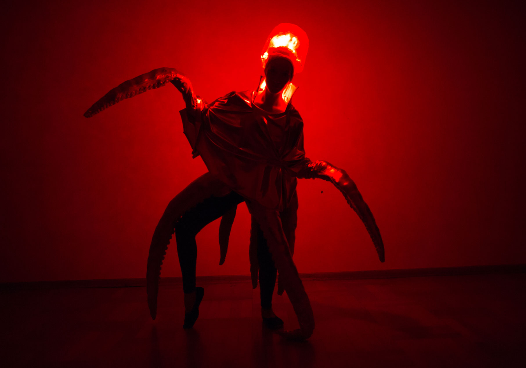
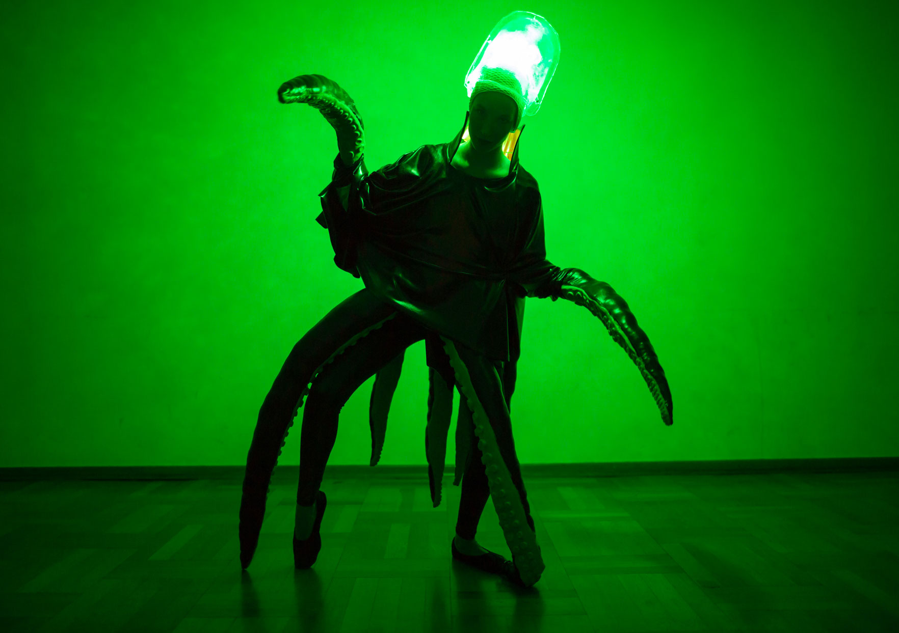
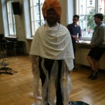
diver, octopus and nemo

The actress had fun with the costume
different mood
diver, octopus and nemo
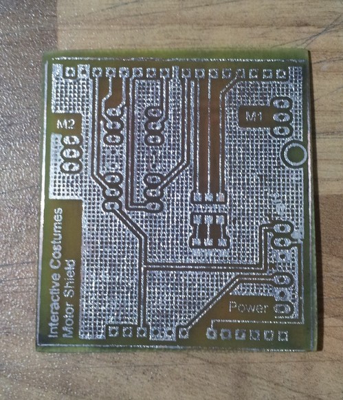
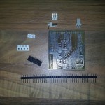
For rapid prototyping it is often useful to have circuits on a circuit board instead of a breadboard. In this post I will give a short description of how you can make your own PCB’s in a fast and cheap way with the so called Toner-Transfer Method. This process require some training, so don’t be upset if it doesn’t work the first ten times.
To develop own PCB’s you have six steps to do:
I consider that you have your schematic and board design finished with the CAD program of your choice. I will use a two-sided layout.
At first export the top and bottom side of your board design as image, and arrange them next to each other. You have to mirror the top layout in order to transfer it in the correct manner onto the PCB later.
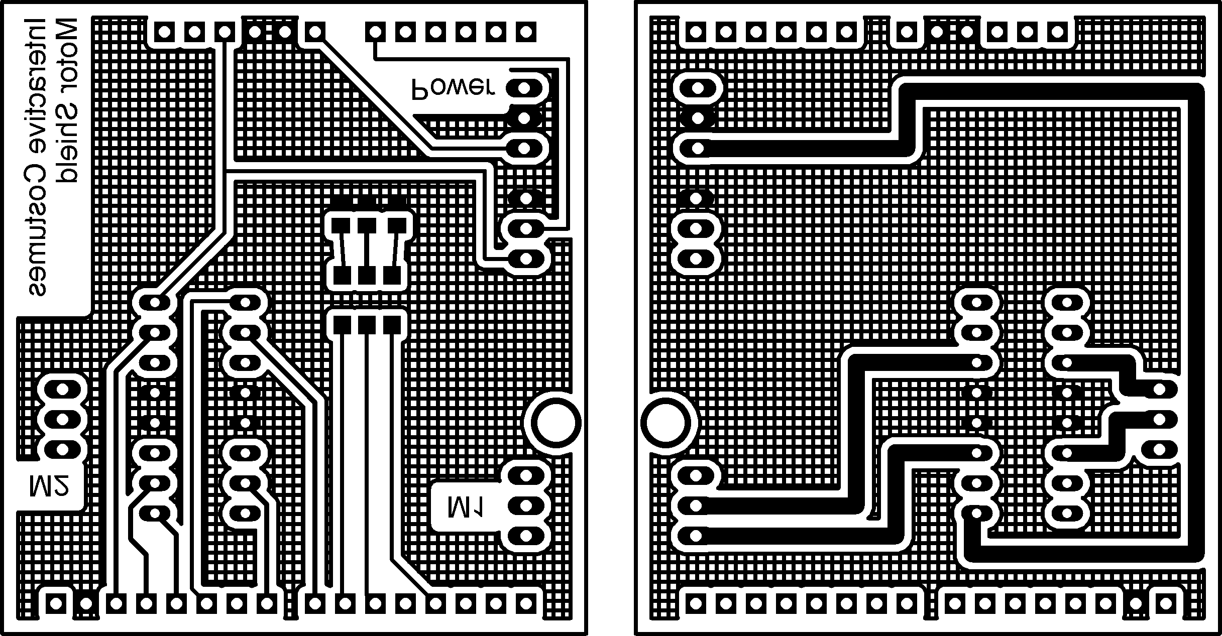
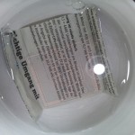
Next you have to print this image with a laser printer on a glossy paper. This prevents the toner from being soaked by the paper completely. It is advisable to print it several times to have some if it doesn’t work the first time.

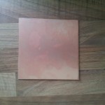
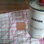
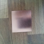
The second preprocessing step is to prepare the circuit board for the transfer. At first cut a piece of circuit board in the dimensions of your layout. Next you have to clean it really good. At first use steel wool for a rough cleaning of the board. After this use acetone to really get rid of all dirt and fat. After this procedure the copper should be shiny like a mirror. During the cleaning and transferring you should wear gloves to ensure the copper stays clean.
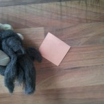
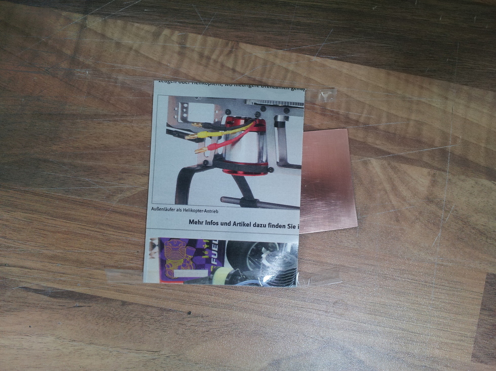
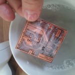
After you have your design on glossy paper and the circuit board is clean, they should come together. Because I have a two-sided layout, I have to ensure that all holes are on the same position for both sides. Therefore, you can build a small bag for the circuit board. Fold the glossy paper with the design so that both sides lie exactly on top of each other. Use duct tape to fix two other sides. Insert your circuit board from the fourth side and place it such that the design borders fit with the circuit board edges.
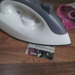
Now you have to transfer the design onto the circuit board. Therefore, you can use an electric iron. It is advisable to put some cotton rag between the electric iron and the paper. Adjust the electric iron to cotton temperature (This may vary with other electric irons). And start ironing the design.
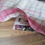
After 5 minutes the toner should be hot enough to stick to the copper. Put the (!HOT!) circuit board in a bowl with cold soap water and wait another 5-10 minutes. Then the catalog paper will dissolve. You can carefully rub over the circuit board to remove the last catalog paper.
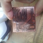
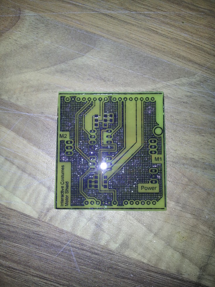
As result, you have a copper board with your design on both sides printed.
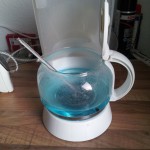
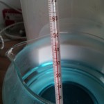
Now comes the interesting part. To etch your layout you need some Sodium Persulfate (NA2S2O8). It should have a temperature around 50°C (not more!). I use the hot plate of an old coffee maker to heat the etchant. Be careful, the etchant will make holes in fabrics, so don’t drip at your clothes (and be careful with your skin as well).
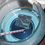
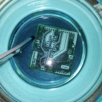
After some minutes you can see how the copper disappears from the circuit board. The toner prevents the design part from being removed by the etchant.
 Next you have to remove the toner. Therefore, you can use again acetone.
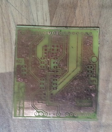
Now your circuit is on the circuit board!
To prevent the copper from oxidating it is necessary to tin-coat it. For this purpose I use Rosol 3 which is available in the hardware store.
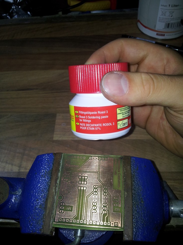
Just brush a thin layer of the Rosol 3 onto the circuit board.
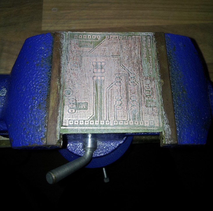
Next use a heat gun to heat the tin until it starts to melt.
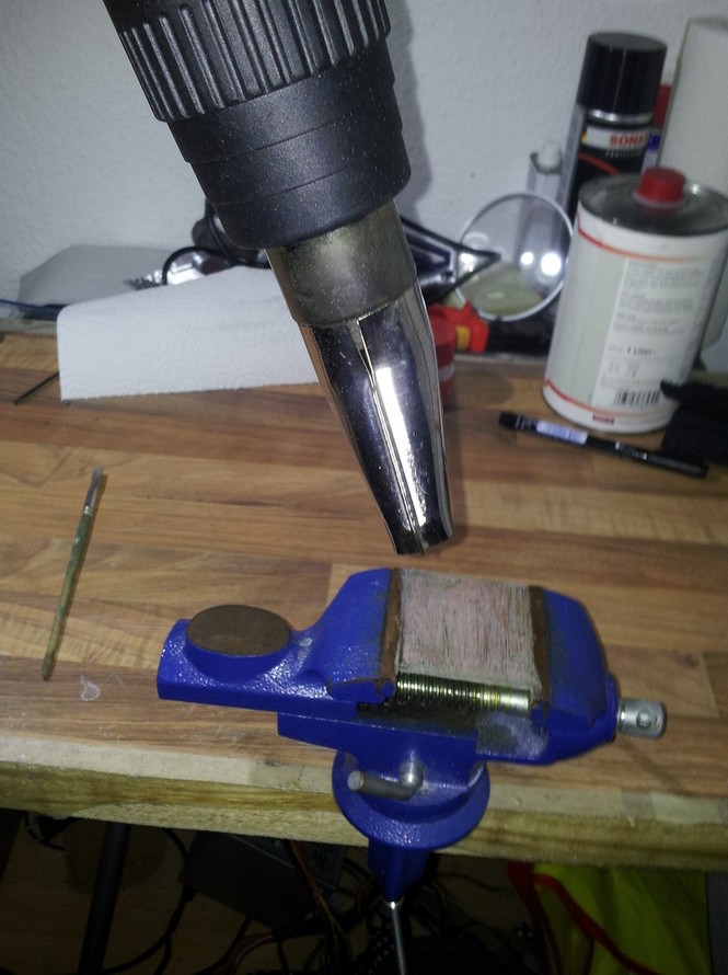
Your circuit board is now silver and protected against oxidation.
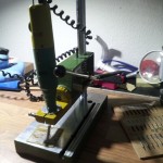
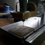
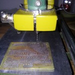
To assemble the parts to your circuit board you need to drill all the holes. I use a small Proxxon drill with drill rig. Connectors need holes with a diameter of 1.0mm, DIP packages need 0.8mm.
After this step you are nearly finished!

Last but not least you have to assemble your parts and test your circuit .
Original: Maranan,D., Alaoui, S., Schiphorst, T., Pasquier, P., Subyen,P., Bartram, L. (2014). Designing For Movement: Evaluating Computational Models using LMA Effort Qualities. CHI 2014, One of a CHInd, Toronto, ON, Canada p.991-1000
Authors: Diego Silang Maranan, Sarah Fdili Alaoui, Thecla Schiphorst, Philippe Pasquier,Pattarawut Subyen, Lyn Bartram
Keywords: Movement recognition; Movement analysis; Laban Effort
analysis; Movement analysis; Movement-based interaction.
Summary: In the paper a new framework for recognizing Laban Effort qualities in real-time is explained. It uses a five degree of freedom single accelerometer input stream, Machine Learning mechanisms and Laban Movement Analysis to detect and classify movement quality.
Main Contents: The paper describes a system called EffortDetect which is able to detect Laban Effort qualities in real-time. In contrast to existing approaches of Effort recognition, which uses position data from movement capturing systems, EffortDetect works with a single 5-DOF accelerometer (X, Y, Z, Pinch, Roll) input stream to determine qualifiers for the movement.
EffortDetect uses Machine Learning mechanisms to classify movements. Therefore, a supervised learning scheme is applied. In the training phase a professional Laban Movement Analyst recorded some exact Basic Effort Actions (BEAs) with the accelerometer attached to his wrist. The gathered data is then used to train the classifier. In the performance phase other (professional) dancers execute the same BEAs (under supervision of the expert) and EffortDetect computes classifiers for the BEAs and outputs the most likely BEA based on the trained data in real-time.
After the first tests some additional mainly mathematical improvements for weighting different BEA profiles were conducted.
EffortDetect has been successfully used in at least two real dance performances.
The eight BEAs:
|
# |
EFFORT |
TIME |
SPACE |
FORCE |
|
1 |
PRESS |
Sustained |
Direct |
Strong |
|
2 |
FLICK |
Sudden |
Indirect (flexible) |
Light |
|
3 |
WRING |
Sustained |
Indirect |
Light |
|
4 |
DAB |
Sudden |
Direct |
Light |
|
5 |
SLASH |
Sudden |
Indirect |
Strong |
|
6 |
GLIDE |
Sudden – Sustained |
Direct |
Light |
|
7 |
Thrust (punch) |
Sudden |
Direct |
Strong – Light |
|
8 |
Float |
Sustained |
Direct – Indirect |
Light |
Ideas for costume evaluation: EffortDetect needed mainly quantitative data for the first evaluations, which is not really helpful for us. But in my opinion it is worth mentioning that they developed a (in their opinion) finish prototype before evaluating with real actors/dancers. Because of time struggle we have now the problem that we have to test pre-alpha versions of our prototype which could lead to meaningless results. I think the evaluation should take place after we decide that the prototypes are ready for testing. The other way around (the prototypes have to be finished when the evaluation starts) is inappropriate.
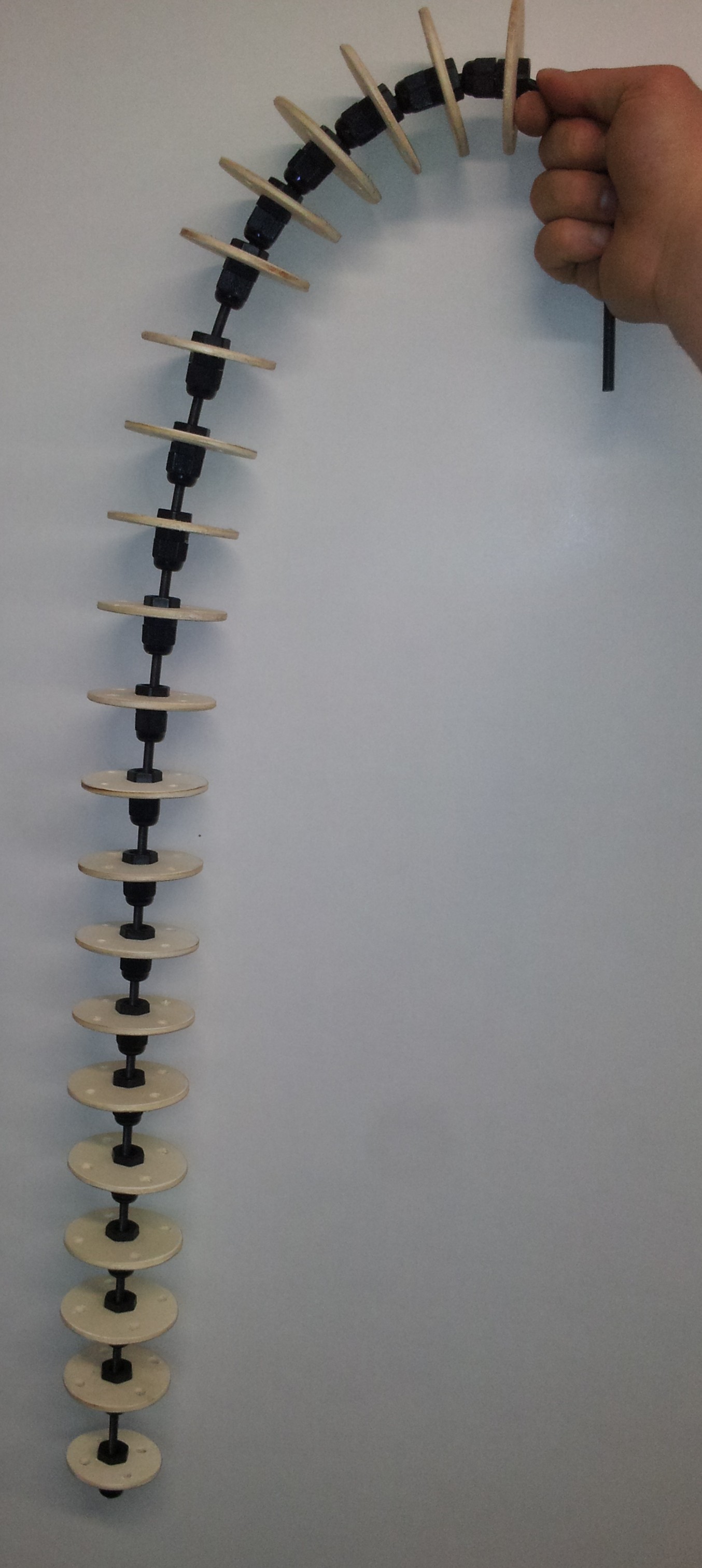
So if you now are interested in how to build your own movable tentacle, I will explain the steps to realize it. This tentacle can be move in two directions ( so along one axis). But for more complex movements the construction stays the same. Only the motor controlling gets more complex to handle more axes.
Materials:
Tools:
Step 1: The wooden disks
At first you need some vertebrae. Therefore you cut 19 disks with a diameter of 68 mm from the pywood. For the tip of the tentacle you can use one wooden disk with 62 mm and one with 58 mm to indicate the end.
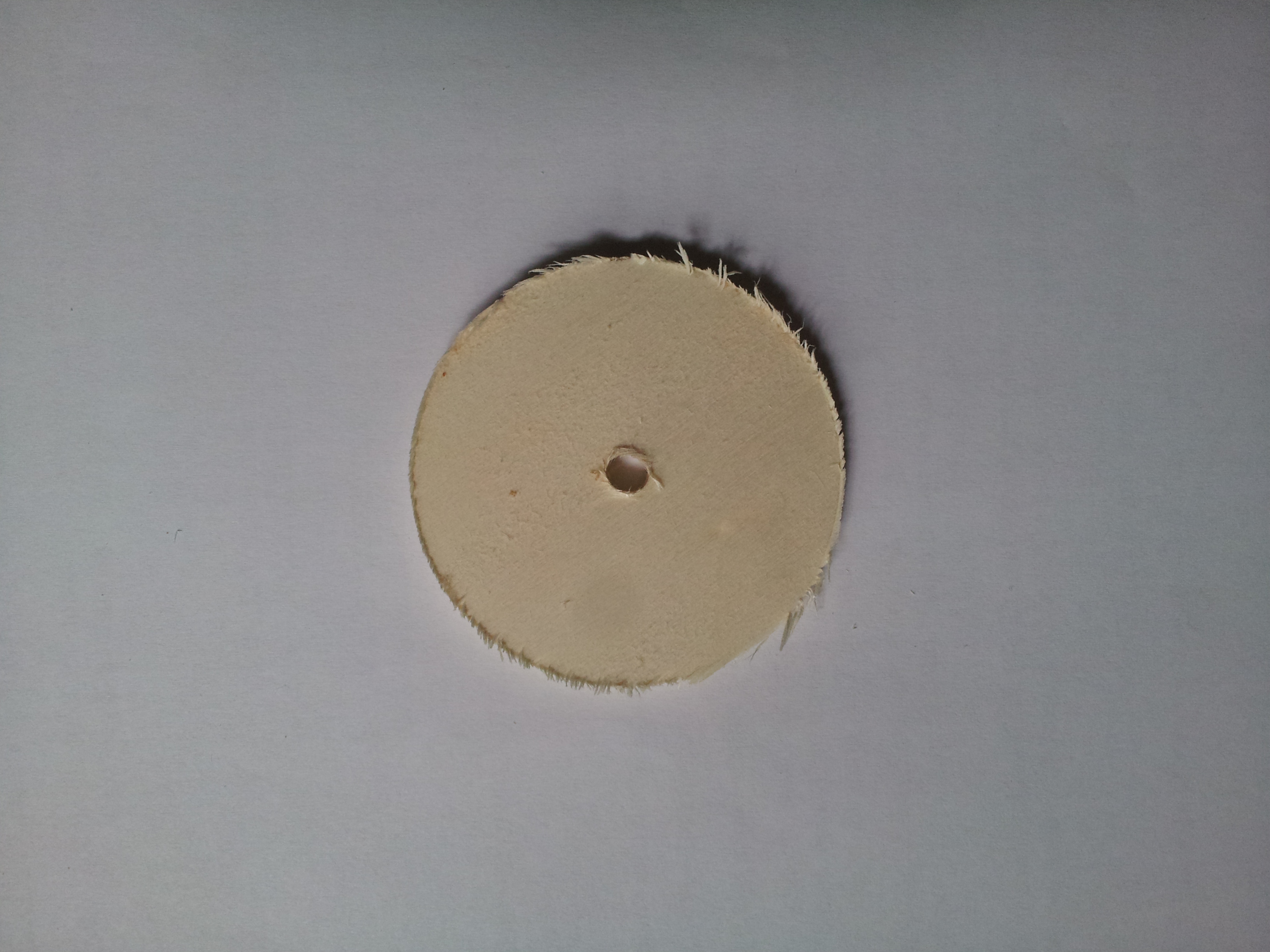
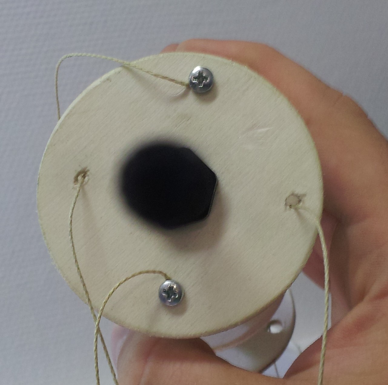
As you can see, after you cut the disk you have to sand it to smooth the edges. Furthermore the hole in the middle of disk which is created by the hole cutter, has to be expanded so that the cable gland screws fit in. Here I used screws with an M12 winding. The result of the sanding and drilling can be seen below.
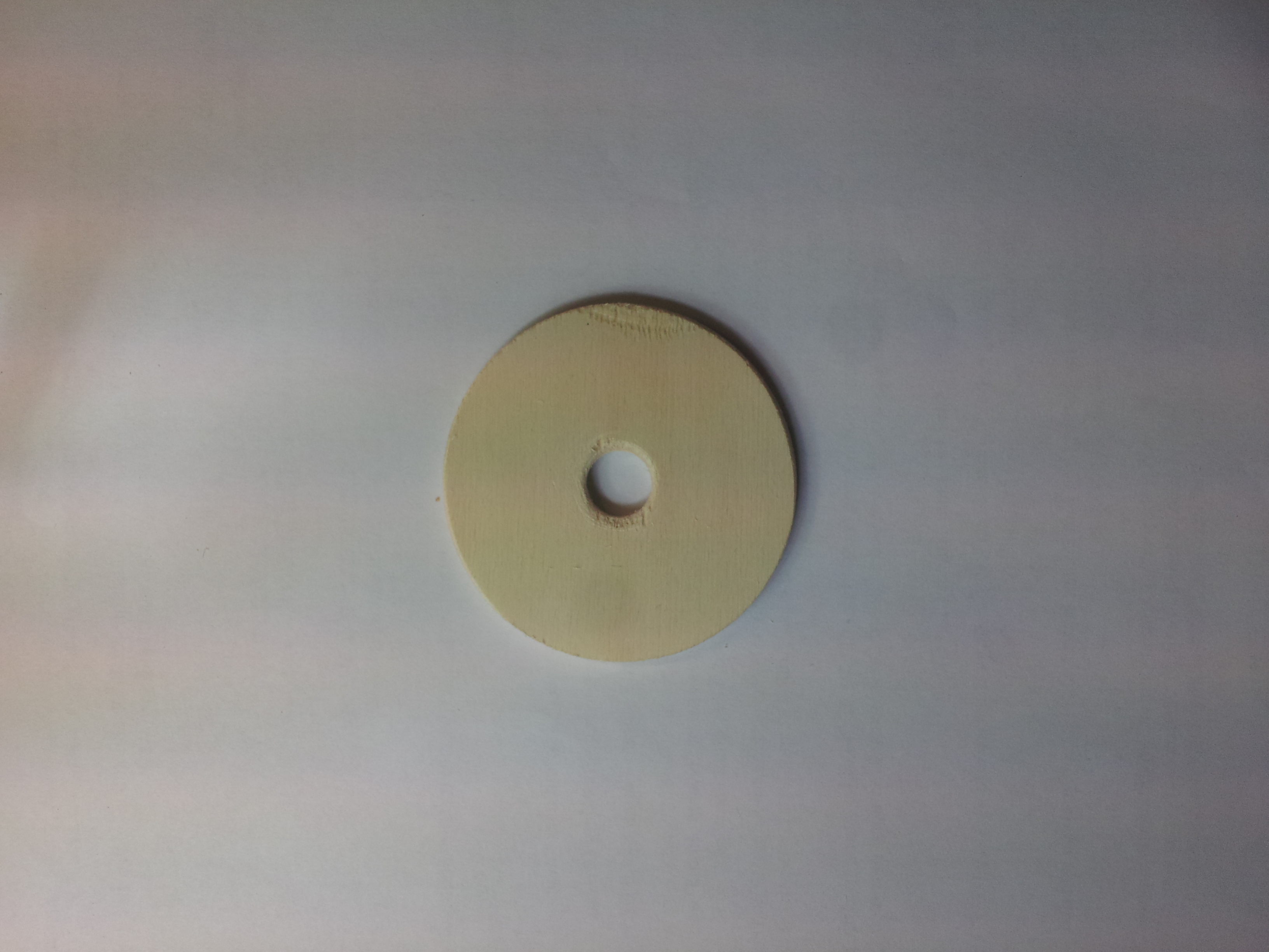
Next you have to drill the holes for the control threads. I used four holes because then we can fix to sides and control two sides for the movement. But if you want to build a tentacle with more movement control, you could use more holes ( you could also use only three holes, then you have to calculate more for the movement; same principle as with the quad-copters). Next you have to drill the holes for the controlling threads. For the big (68 mm) disks I align them on a circle with radius of 24 mm around the center. This is just 1 cm less then the radius of the disk. The diameter of the control holes amounts 5 mm.
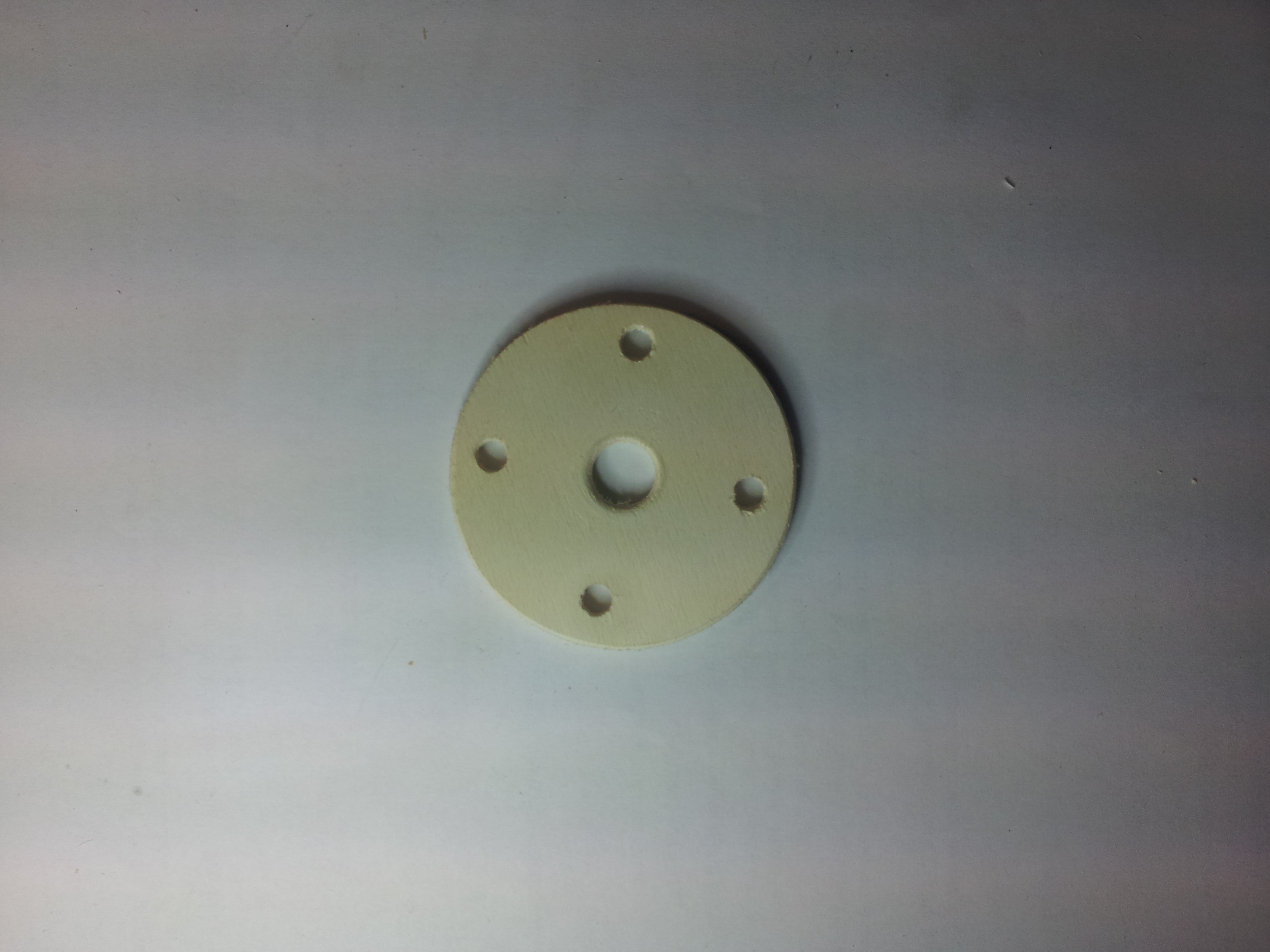
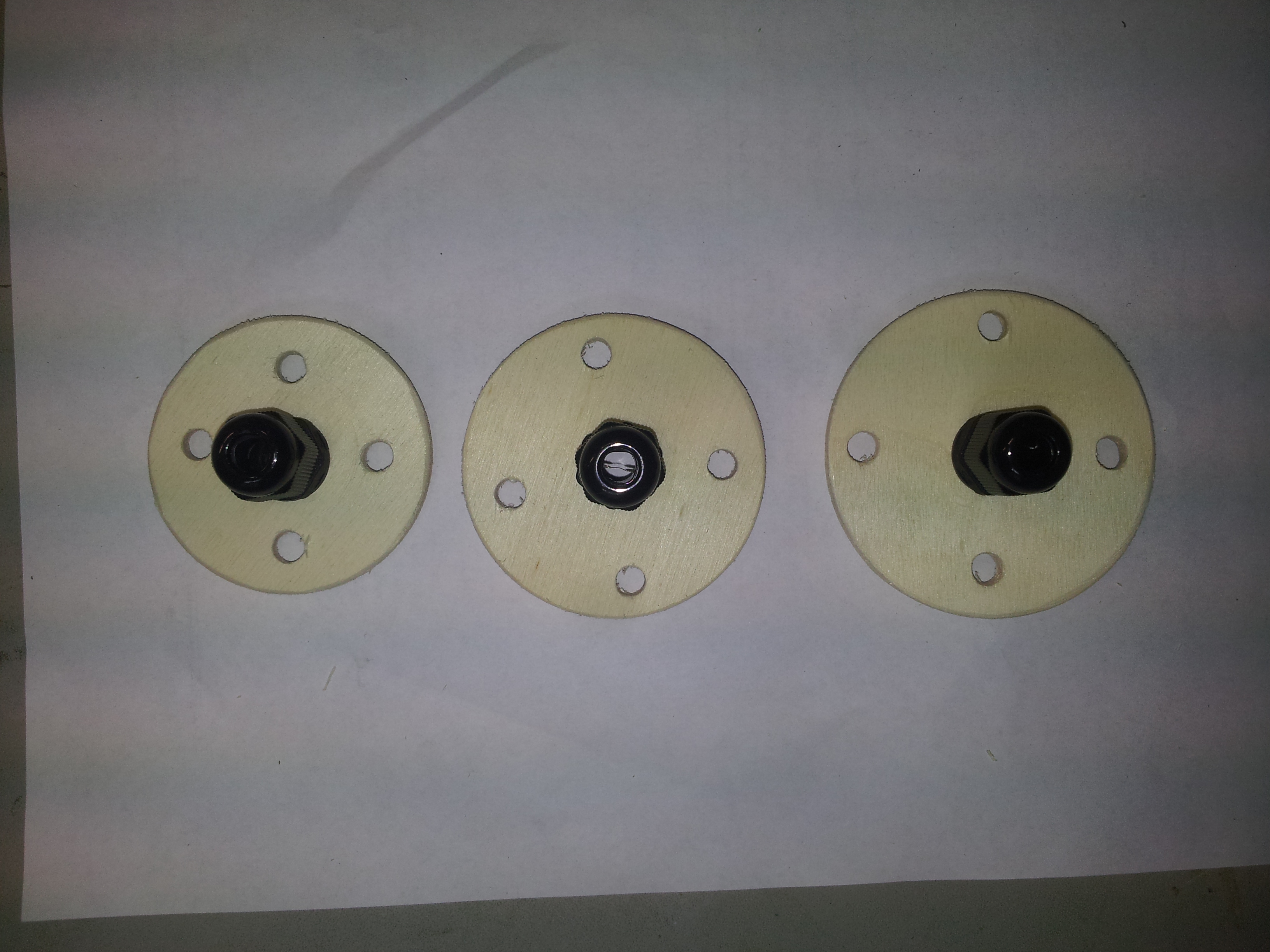
This is how the wooden disk should look after this step. Next you have to apply the cable gland screws and put them aside.
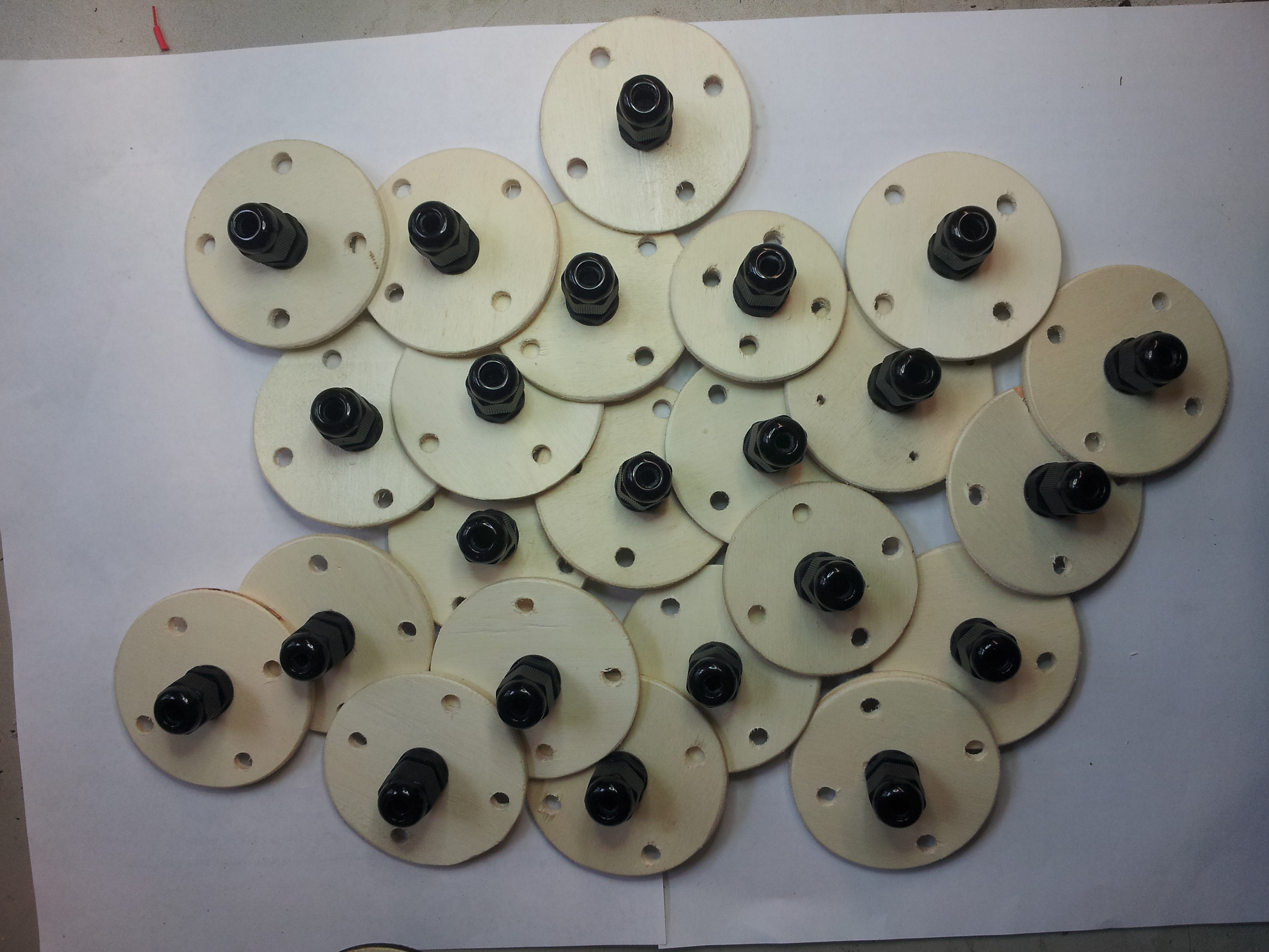
This was the fiddly work. The next steps will be more straight forward.
Step 2: Assembling the spine
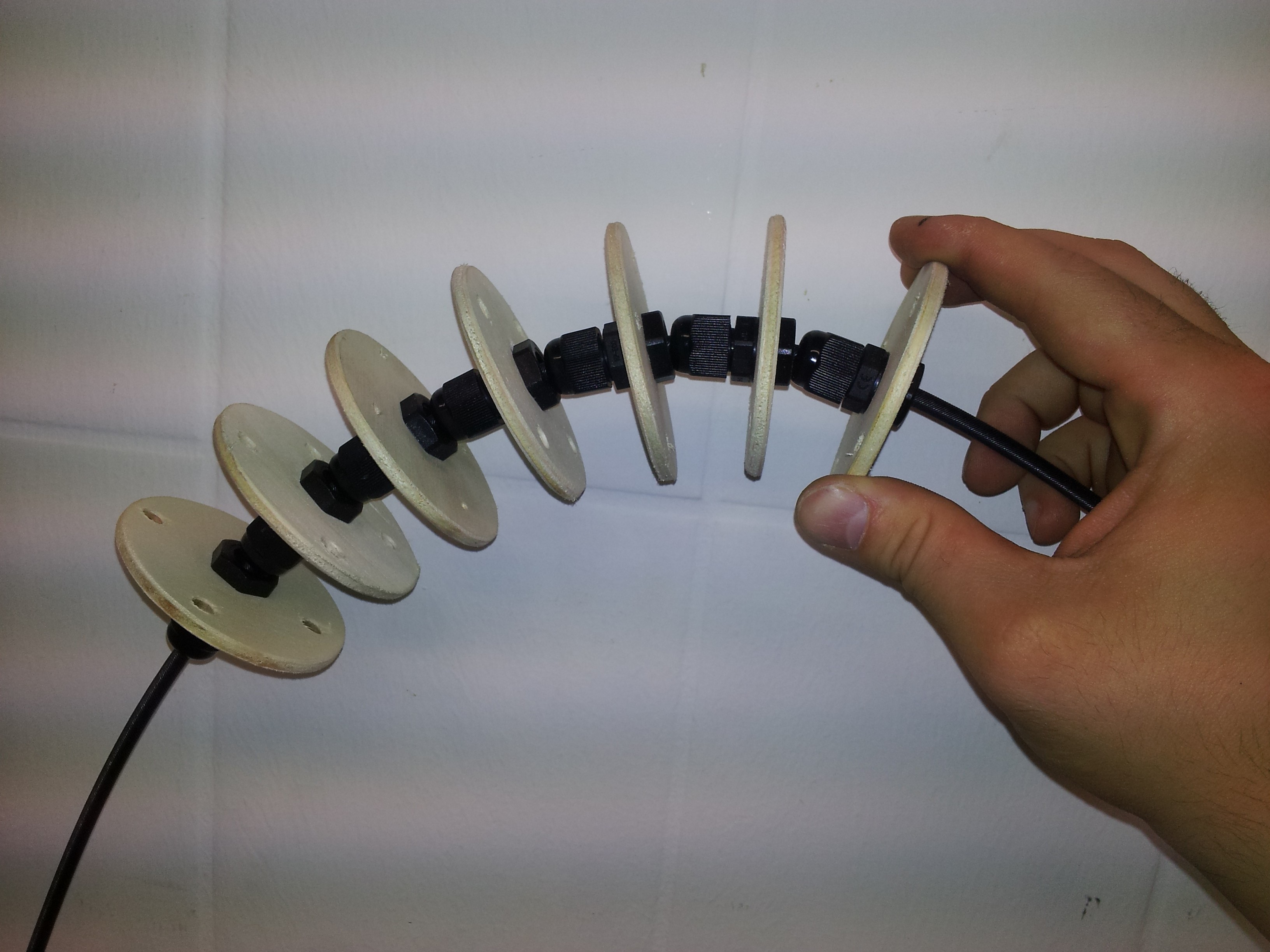
Now you can take the disk with the screws and 1 m of your soul (here the flexible shaft) and put them together. Leave 12 cm from the top of the shaft and place the first disk there. The 12 cm are used to mount the tentacle later to the costumes. The first 6 disks have nearly no space in between to stiffen this part. Therefore it will stick out of the costume a little bit and not just hanging down. The next disks have a distance about 4.5 cm. The two last disks are the smaller one to indicate the tip of the tentacle.

Step 3: Attach the controlling threads
The last step is to attach the controlling threads. I used 1.6 m for the movable threads and 1.2 m for the fixed dimension. You should take care about the tip. To have a smooth movement the threads should placed carefully as you can see below.

This is how the tentacle mechanism is built. The controlling threads are then attached to a motor. The movement will be described in another post.
We want to construct the head of the Octopus with a (semi)transparent illuminated brain part. Therefore we will use the following approach: some thin transparent plastic is heated and then pressed against a massive form. The result will be the half of the form pressed against the plastic disk. So we will have two halves,each of one side of the form.
We decided to take clay as material for the form. So here are some pictures of the result from a three hour pottery session of Dilek and me.
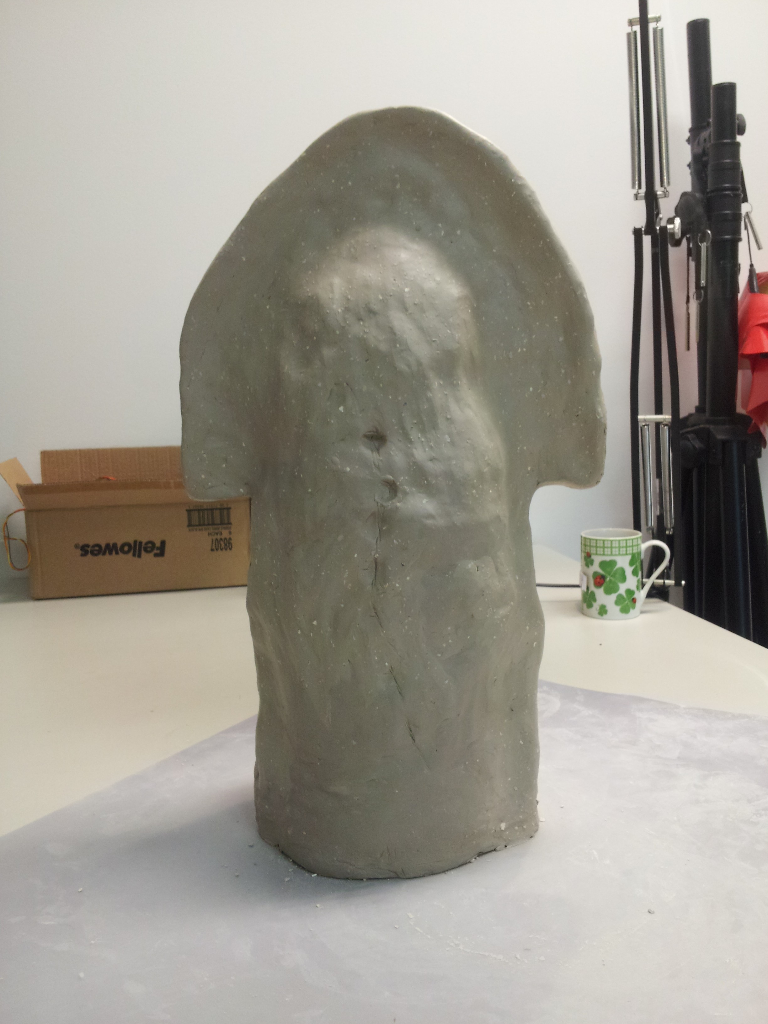
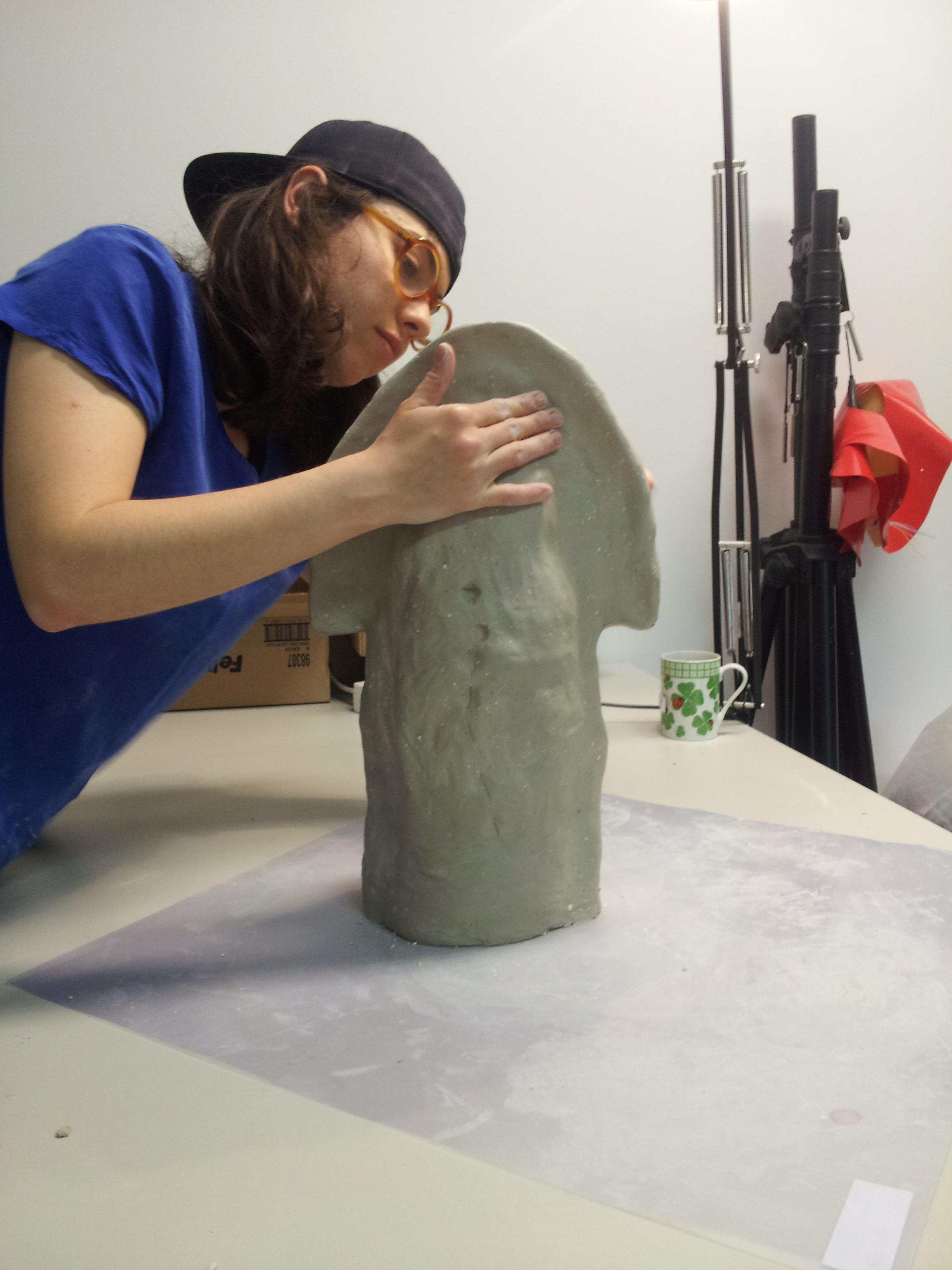
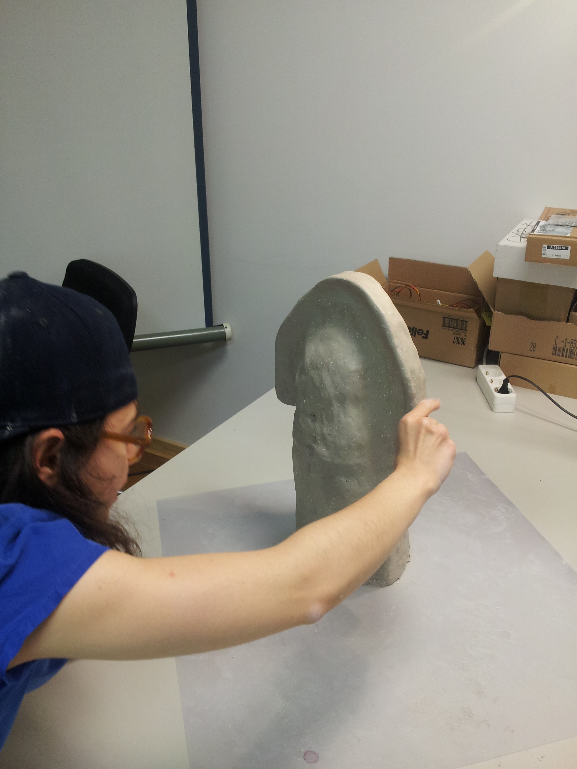
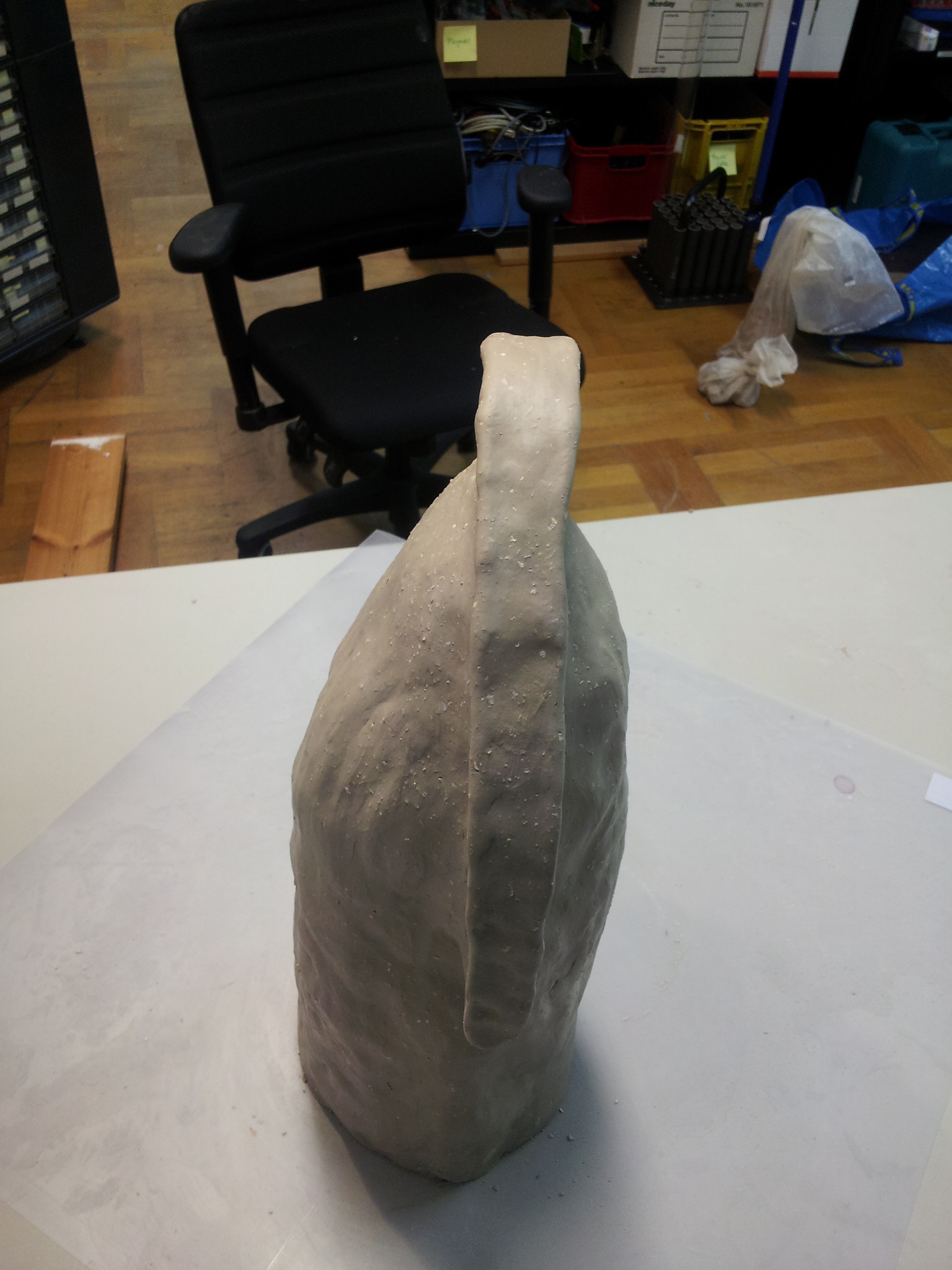
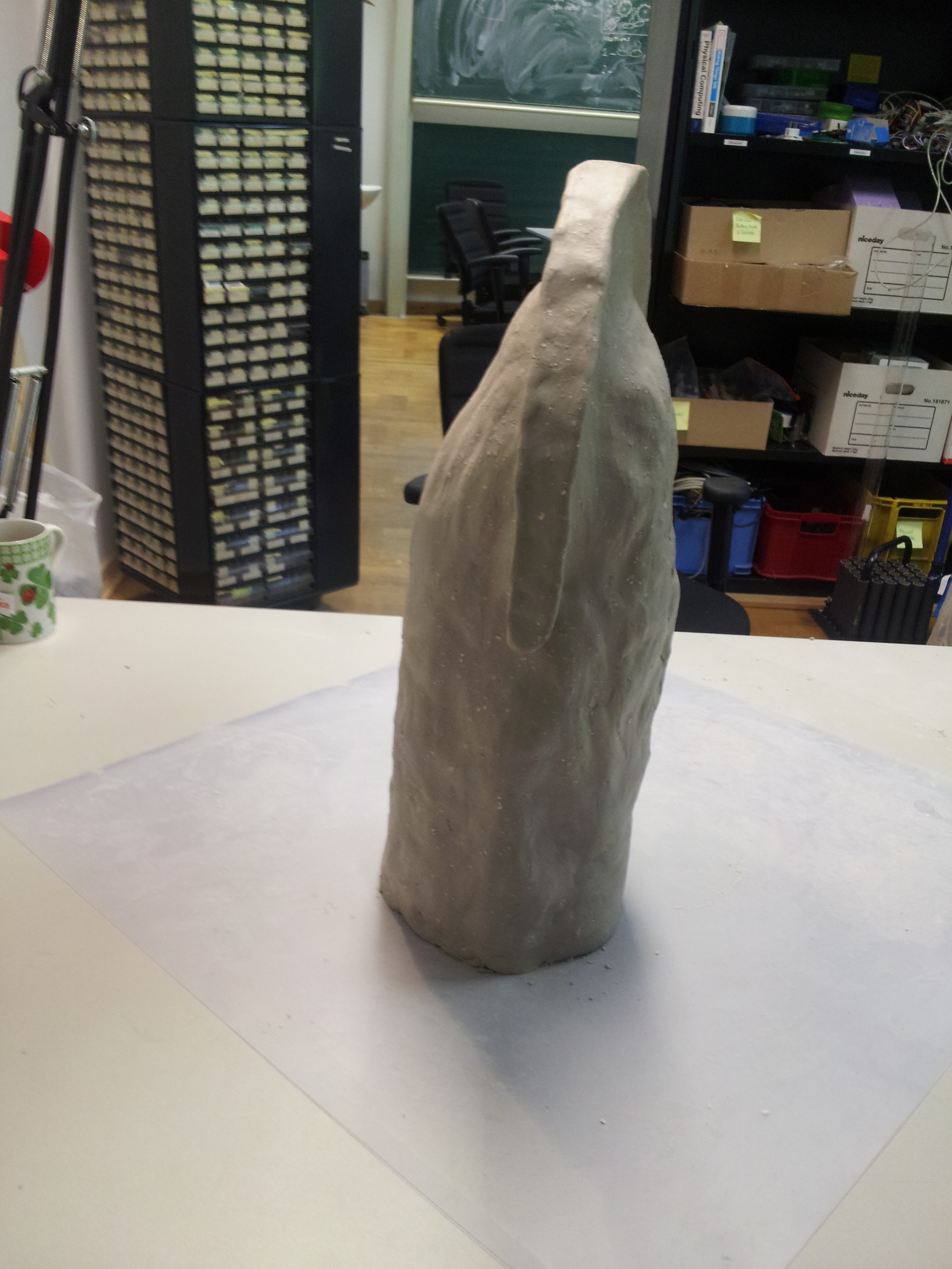

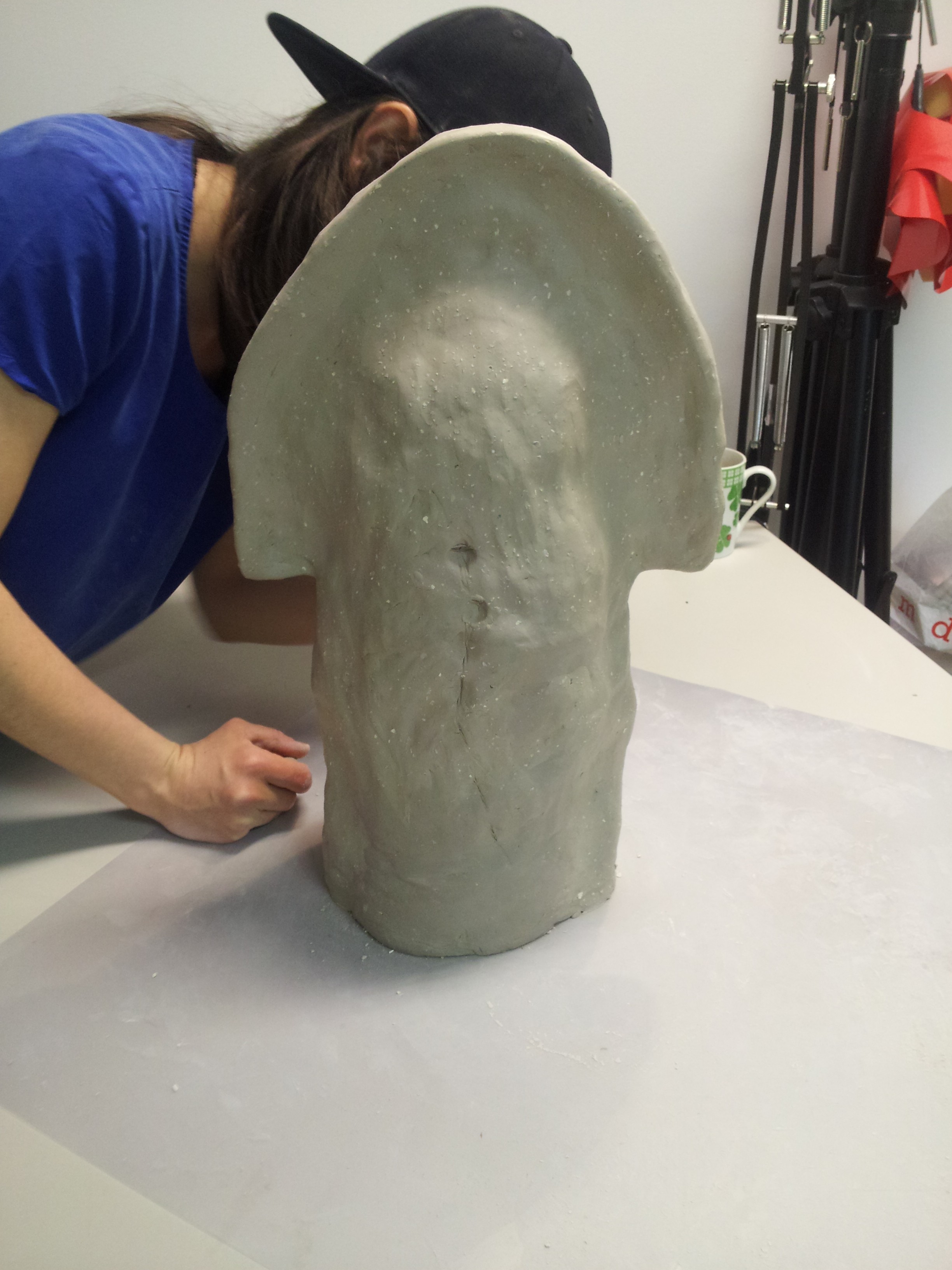
So our result will be a transparent plastic helmet, which we can then design. We are already sure that in the back of the helmet will be drilled many small holes to prevent the actor from sweating to death.
A possible problem could be the weight of the tentacle, but since we have no real scaled tentacle yet, this is just a guess. An actual problem is the movement of the tentacle. If the soul torques to much we won’t get a nice movement, but a twisted mess.
Materials:
(image will follow)
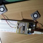
By pulling the steel cables the tentacle moves in the desired direction. The flexible tube torques to much so the movement is limited to a small percentage, until the tentacle twists. For that reason I was searching for other materials as soul for the tentacle. This prototype is not pretty but functional ;).
Materials:
(video will follow)
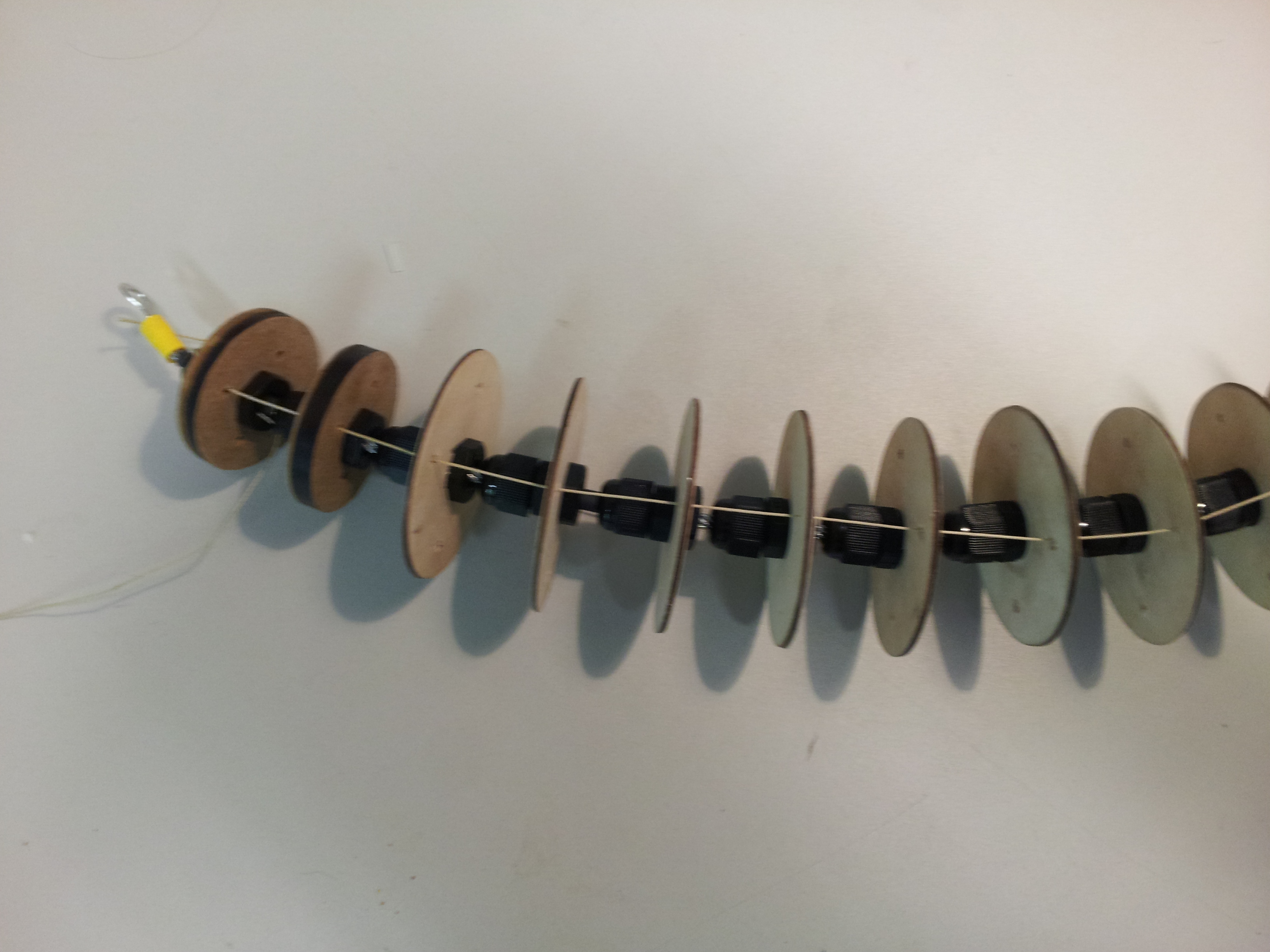
For this approach we used a 4 mm steel cable as soul for the octopus. Furthermore we replaced the flexible tube spacers by cord strain relief grips. The wooden discs have different sizes because we just used some leftover wood. But the result was still not perfect, because the steel cables torques to much.
(video will follow)
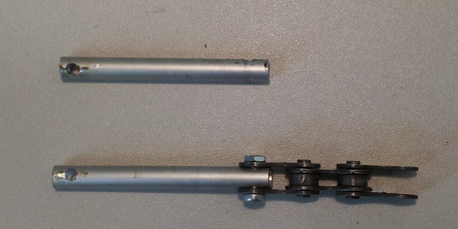
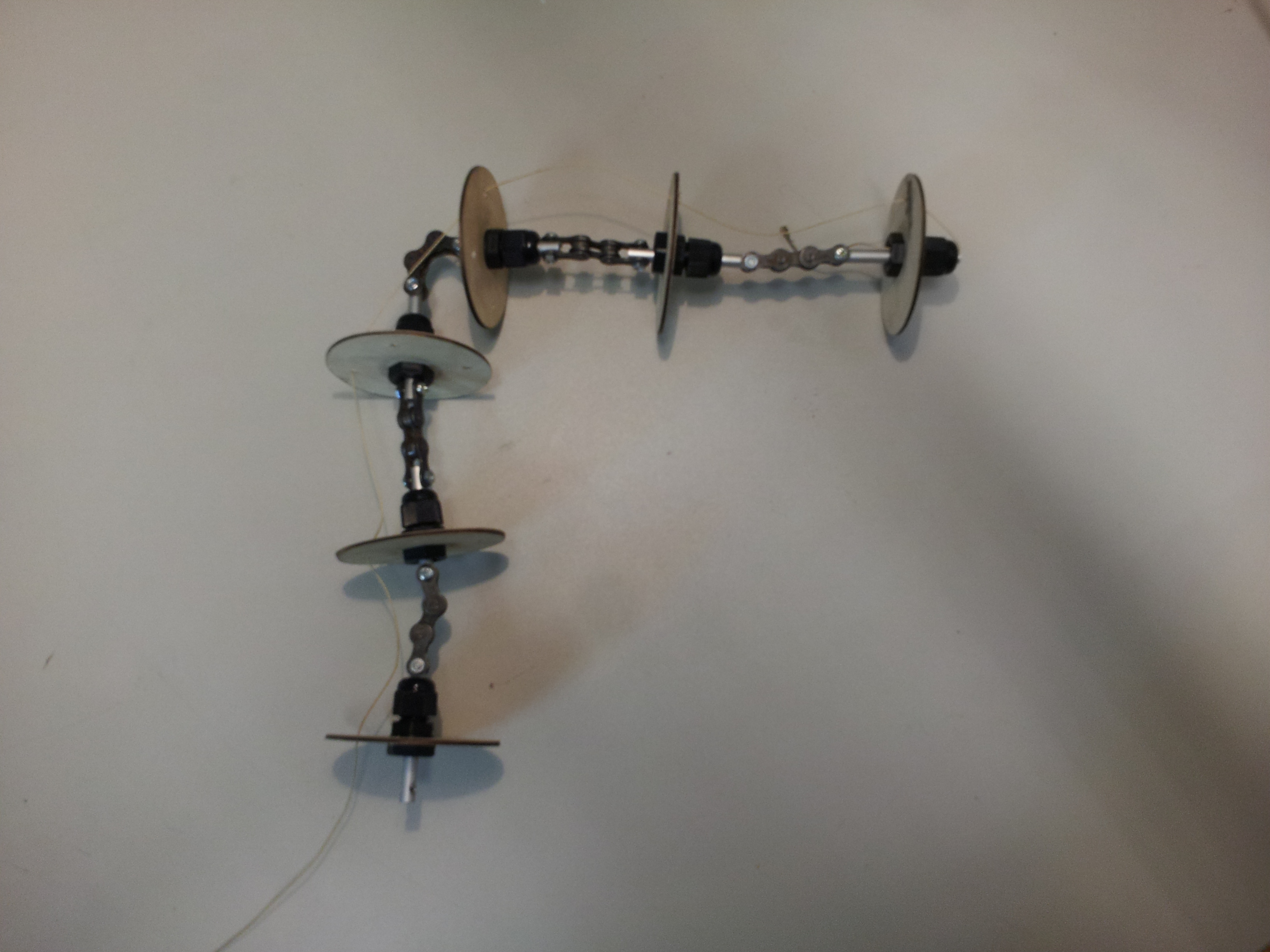
The next idea was to use bicycle chain links to avoid the torsion. Therefore I drilled two holes with 90 degree skew at both ends of a small aluminium pipe. Next I screwed small bicycle chain links to it.
The wooden discs with the cord strain relief grips were attached to the aluminium bar, followed by the next bicycle chain link.
The result looks promising:
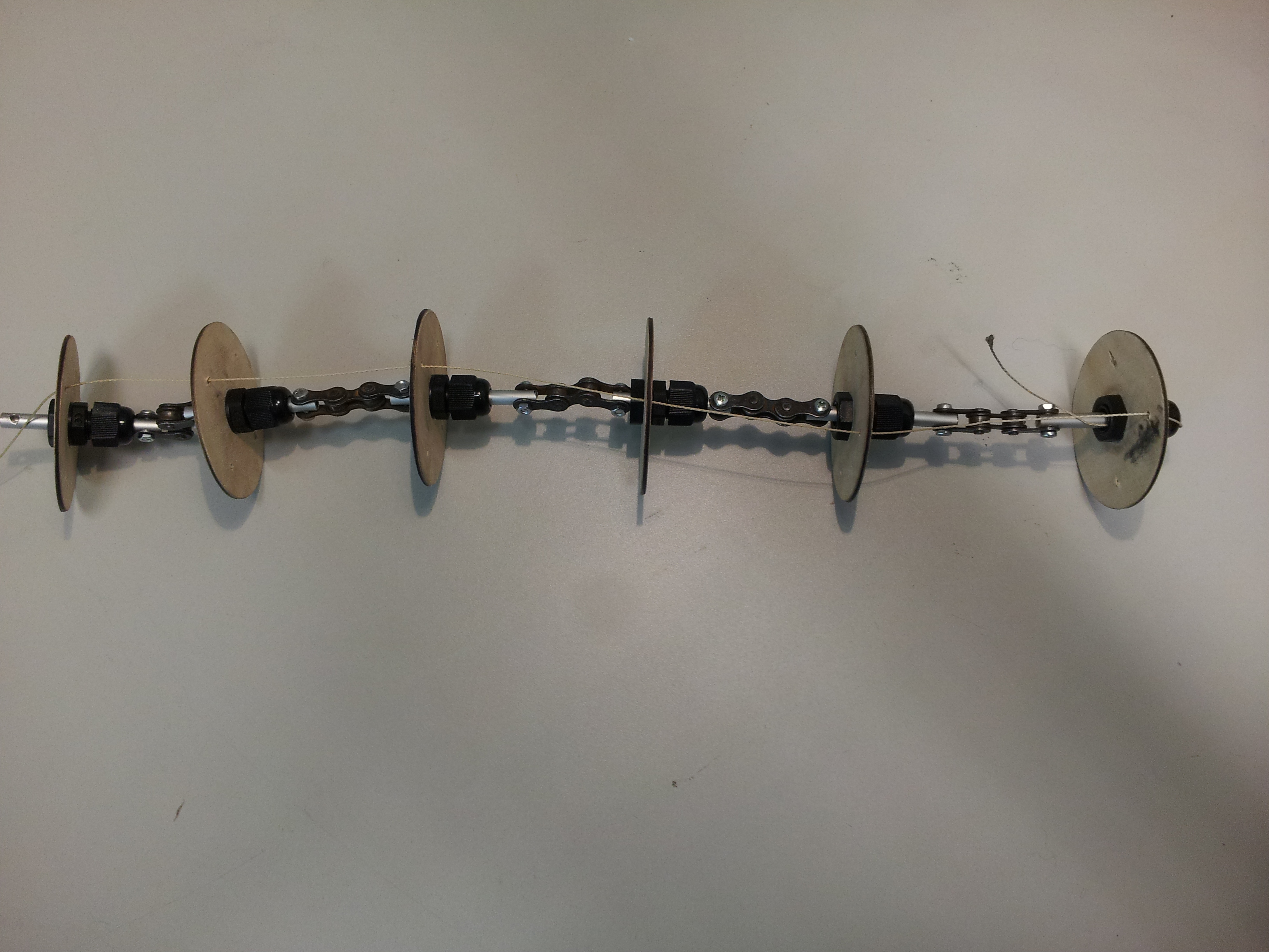
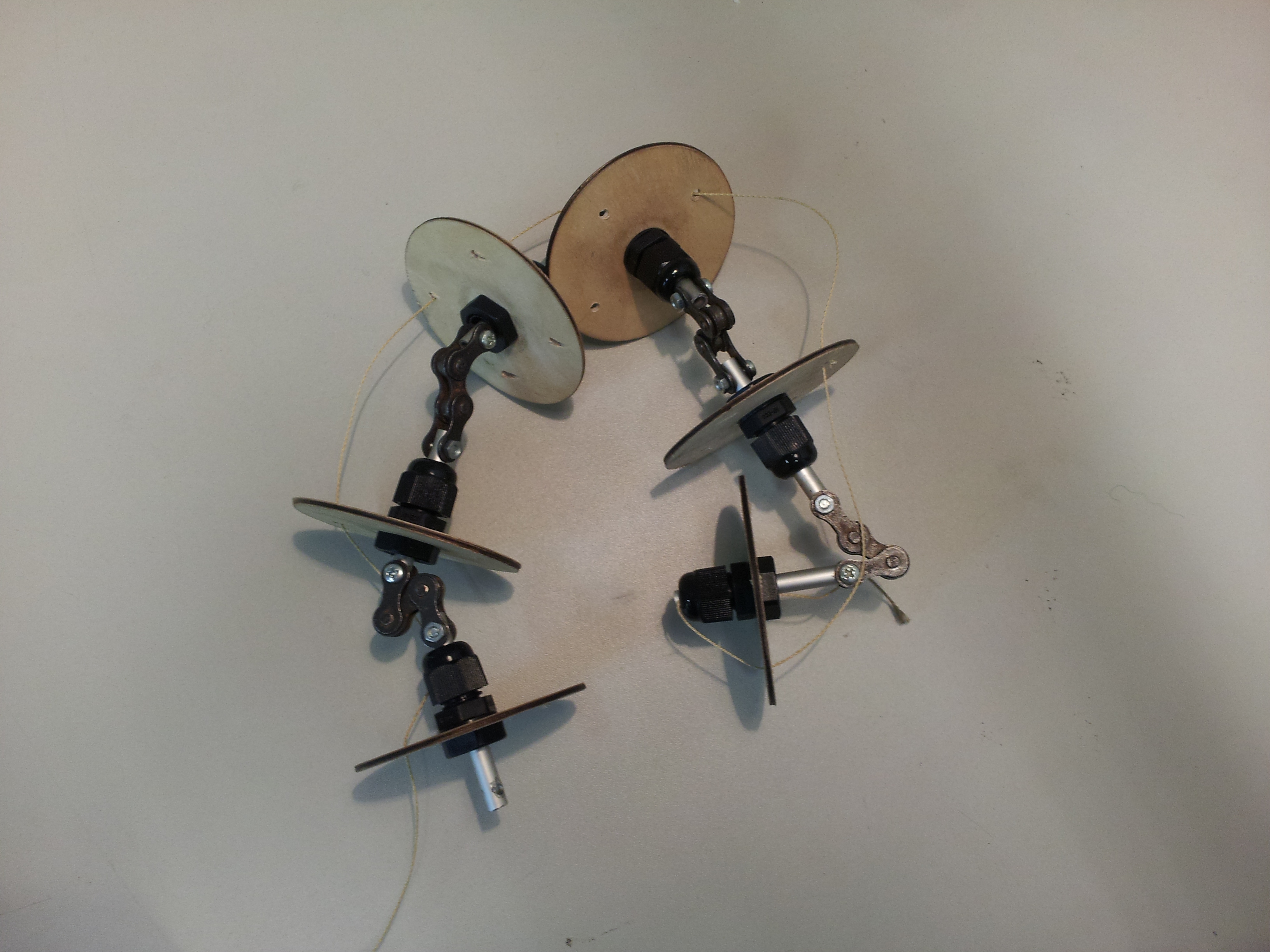
But the movement was really disappointing. It was neither smooth curved nor naturally. In retrospect this result is logical. The single chain links have no resistance along the axes so they just move in an acute angle.
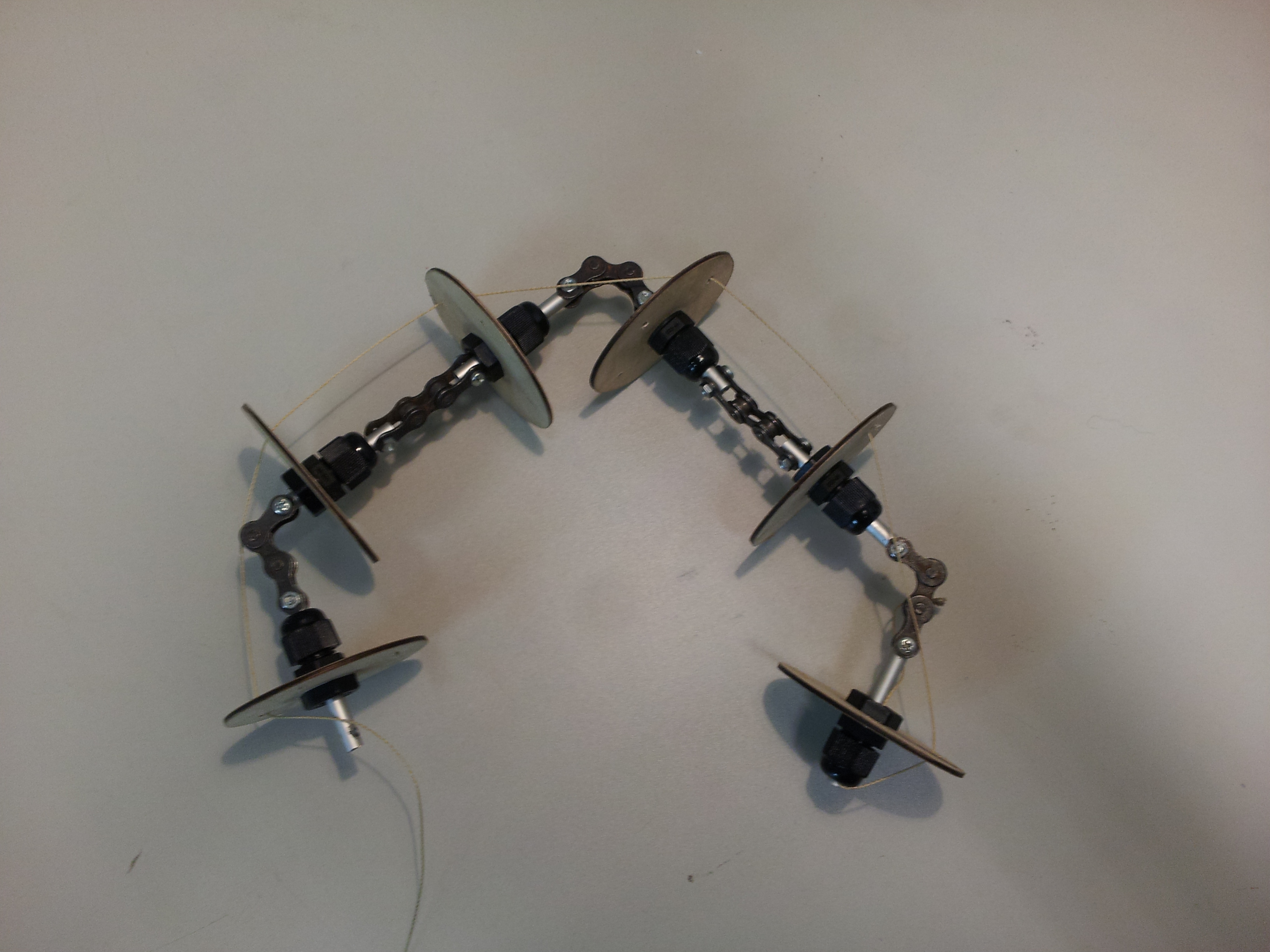
Complete bending results in a total mess:
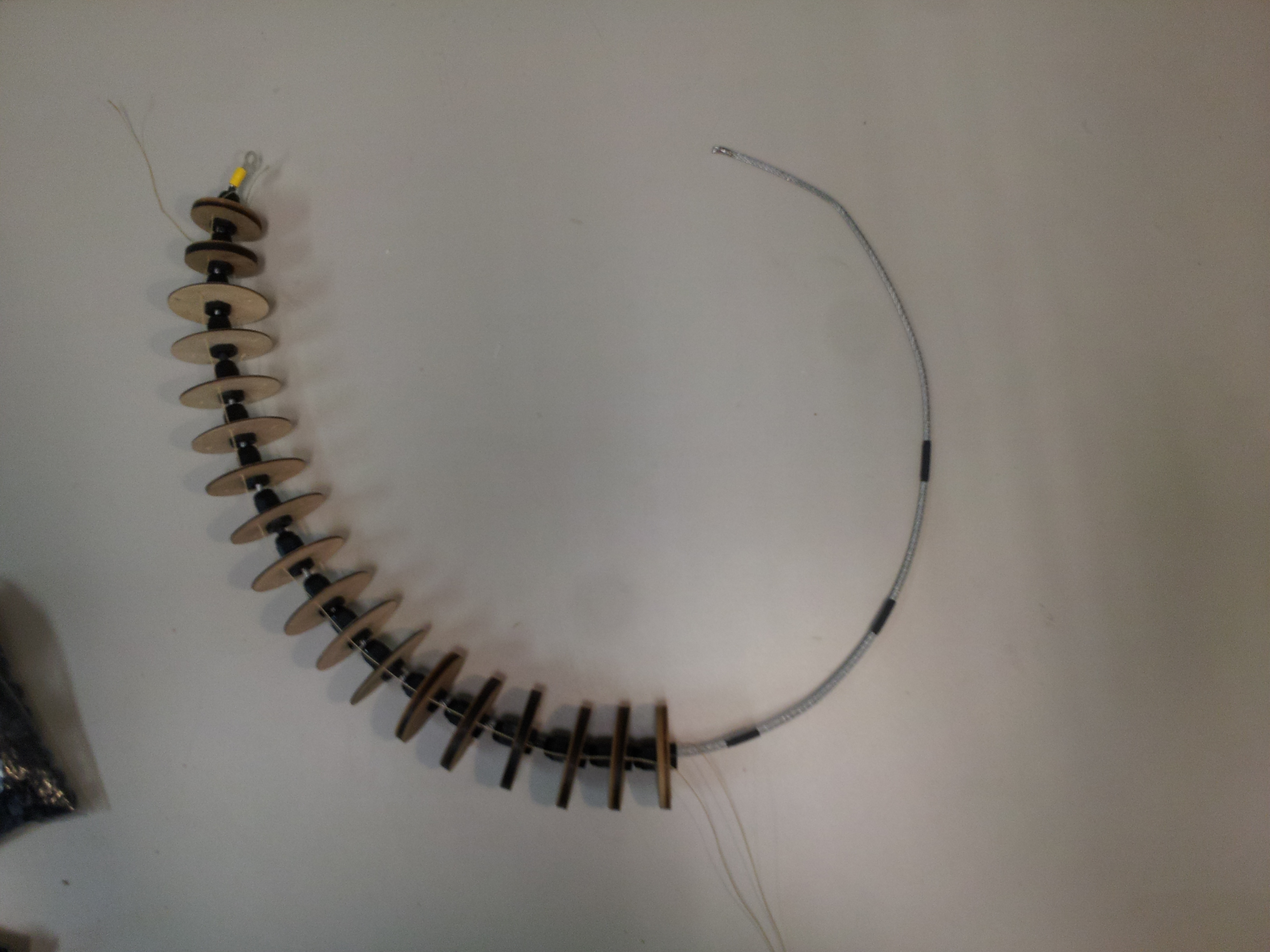
Next I will go back to approach one. Since this approach creates a smooth curve, but torques to much the idea is to use a flexible shaft to reduce the torsion to a minimum.
Since the company GEMO sent us free samples of flexible shafts with a diameter of 4 mm and 5 mm we test them as soul for our tentacles. The results are quite good, so that we will use the flexible shafts and not the steel cable. The main advantage is that the flexible shafts have no twist and can’t torque. So a better controllable movement is possible.
In our bodystorming session we developed first ideas how the octopus could look.


all photos taken by Eva Hornecker
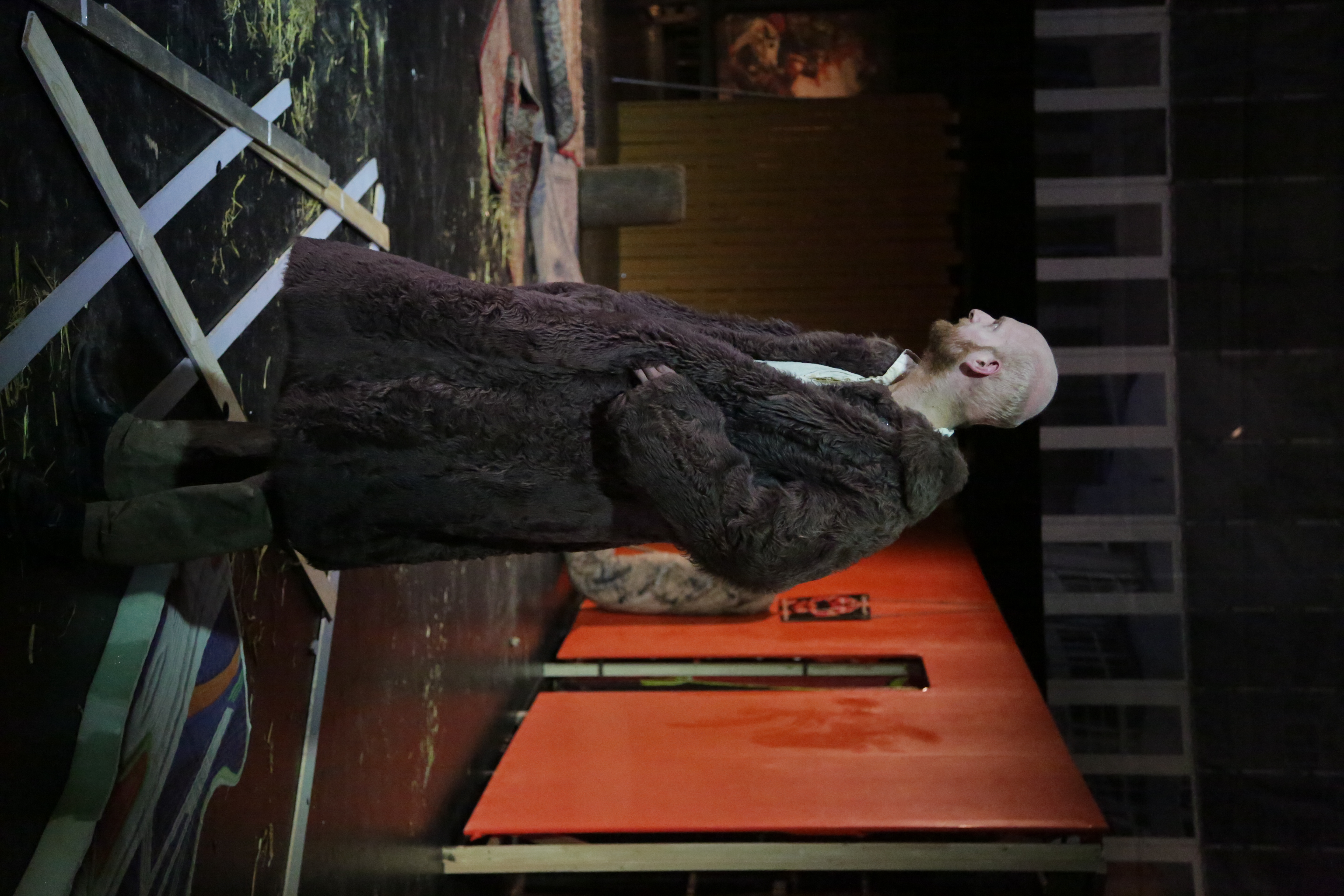
Delirious Jena – Des Lebens Überfluss | Theaterhaus Jena
Text/Direction: Hannes Weiler / Stage: Florian Dietrich / Costumes: Lena Hiebel / Dramaturgy: Friederike Weidner
Focus on Actor: Mathias Znidarec
Heinrichs costume consists of:
With the help of small changes in the costume one can distinguish three different “Heinrichs” during the play
Confused Heinrich
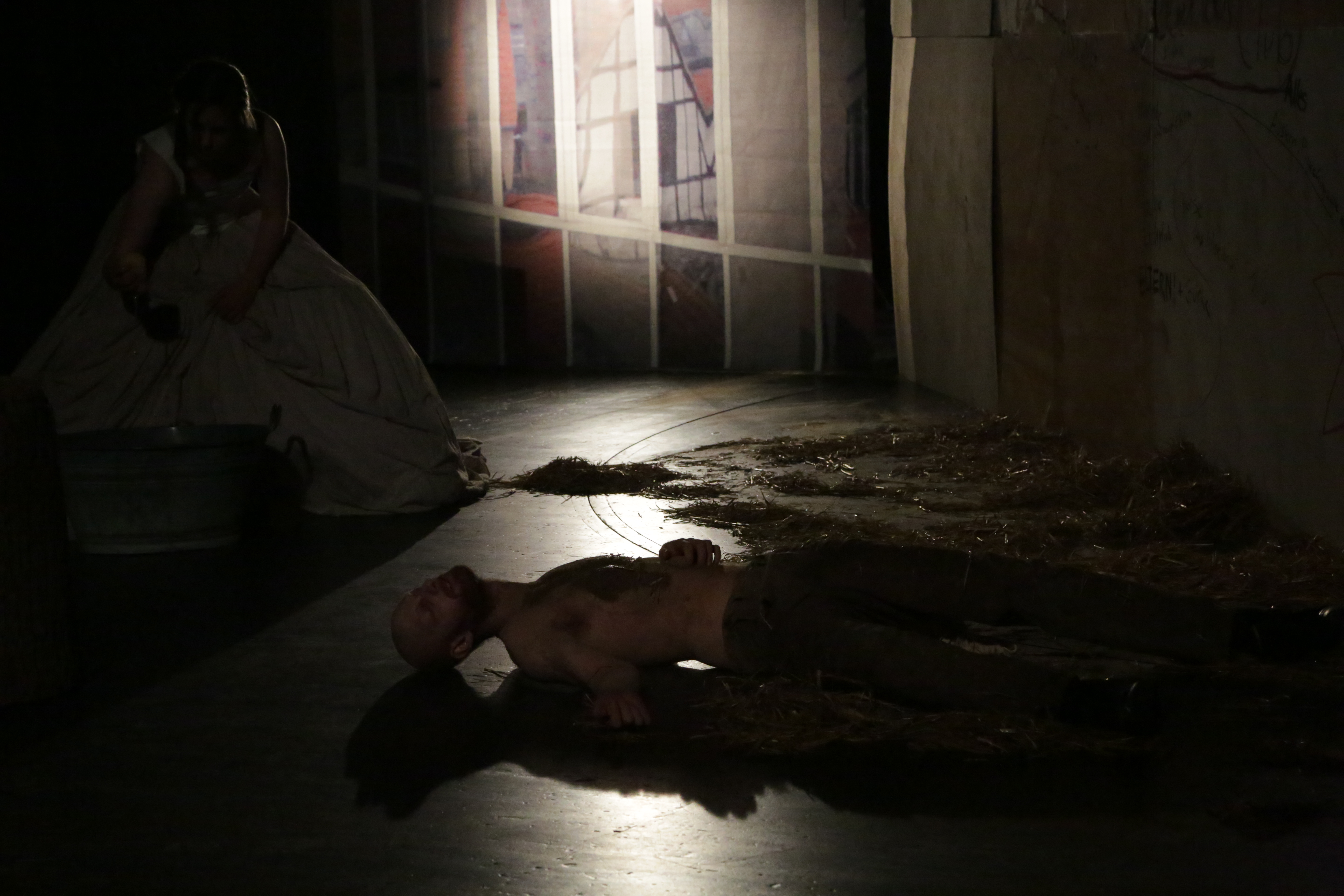
First Heinrich is confused and really thirsty. He even doesn’t recognize his wife. The fact that Heinrich doesn’t wear a shirt but is full of mud emphasizes this crazy state.
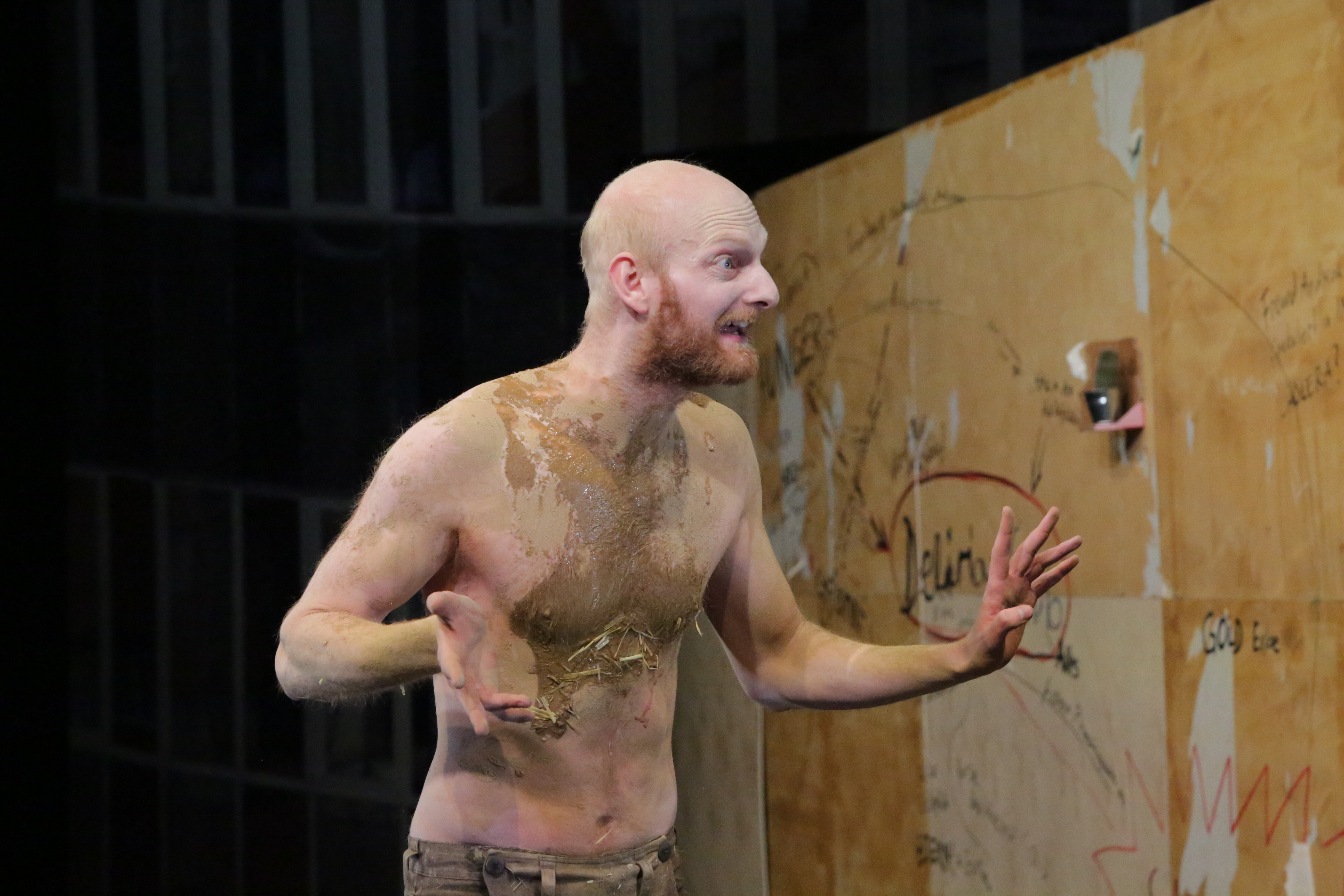
Clear in Mind Heinrich
After Klara (his wife) gives him something to drink, Heinrich gets a clear head. He puts his wide sleeved shirt on which supports his sweeping gestures.

Greedy Heinrich
During the play Heinrich gets greedy for a short moment. He has stolen some gold and doesn’t want to live ascetic anymore. This characteristic is expressed by a big fur coat. His posture changes also.
Back to the Roots Heinrich
At the end Heinrich is poor and hungry again. Because he is also wet his shirt is full of mud now. He looks pretty depressingly.

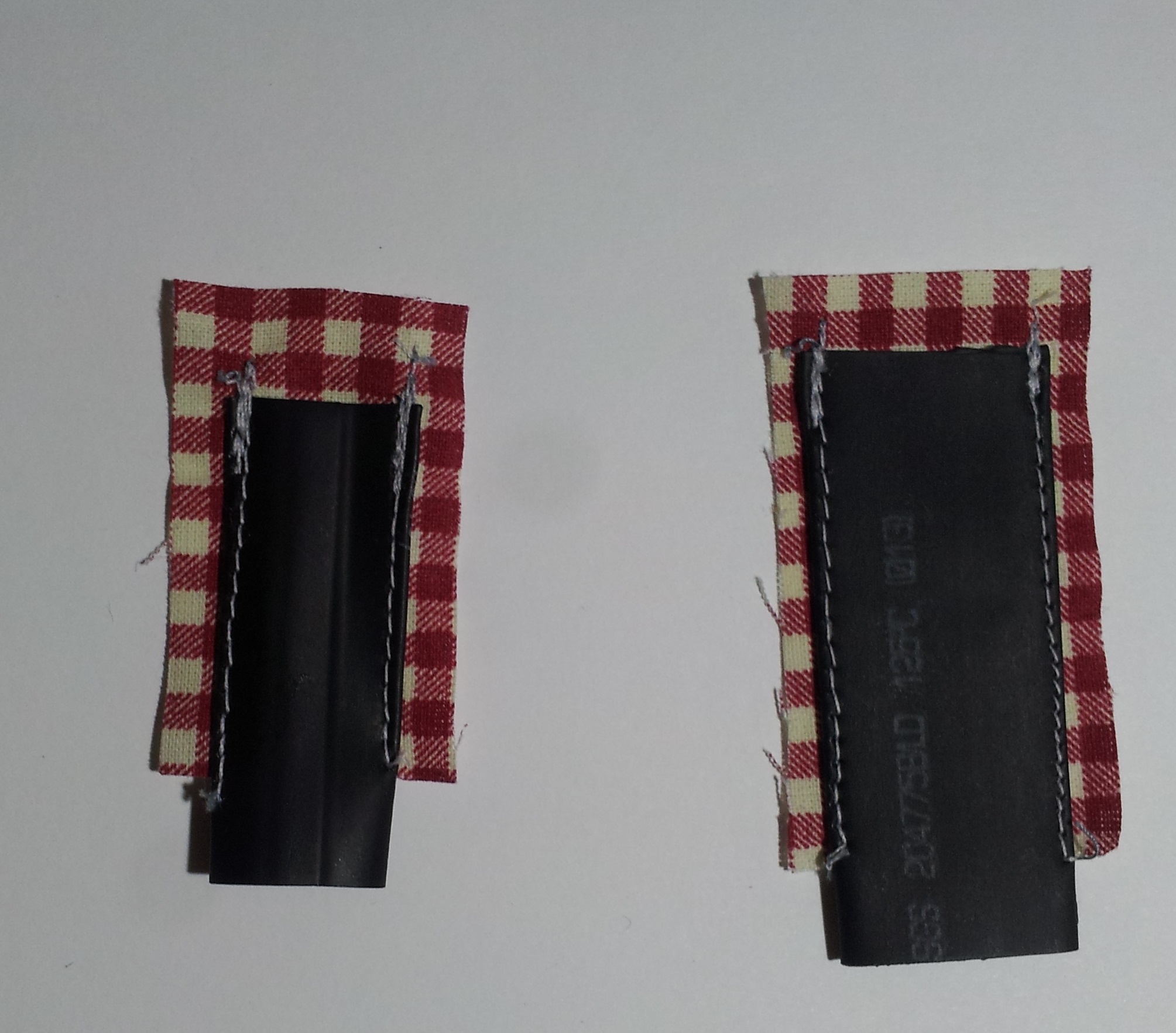
Instead of distributing smoke through tubes and pipes through a costume, one could distribute the fog machines. So the smoke/fog is where it is needed.
Since E-Cigarettes work with the same principle as fog machines, they are an option for small, low-cost and low-power-consuming fog machines. Furthermore E-Cigarettes are small enough to put them nearly everywhere inside (and outside) of a costume.
In contrast to fog machines, E-Cigarettes have the advantage that they are cheap. Simple versions start at 20€; therefore, plenty of them could take placed instead of one fog machine

To spread the smoke small pumps can be used (something like this).
If it is needed to transport the fog over small distances, shrinkable sleeves may be a good possibility. They are flexible and sew-able. And since they are shrinkable they can easily be used to drain off the transition from the pump.