Category Archives: Octopus by DIMATH
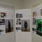
Final Exhibition Summary / Open Lab Night

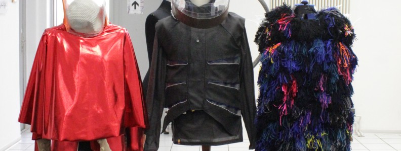
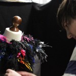
Design Acting – Octopus
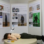
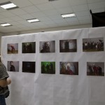
Photos from design acting workshop
The actress had fun with the costume
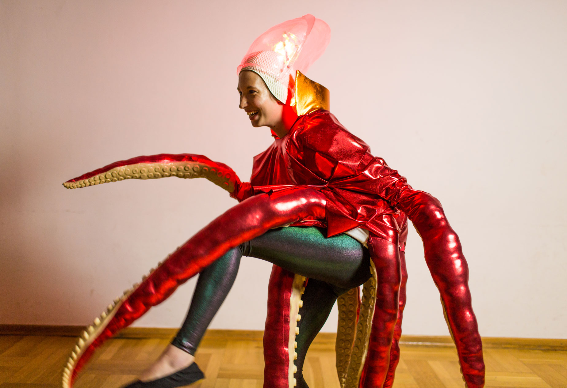
different mood
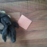
diver, octopus and nemo
Homemade PCB
For rapid prototyping it is often useful to have circuits on a circuit board instead of a breadboard. In this post I will give a short description of how you can make your own PCB’s in a fast and cheap way with the so called Toner-Transfer Method. This process require some training, so don’t be upset if it doesn’t work the first ten times.
To develop own PCB’s you have six steps to do:
- Preprocessing
- Transfer layout
- Etch
- Postprocessing
- Drill
- Assemble
I consider that you have your schematic and board design finished with the CAD program of your choice. I will use a two-sided layout.
Preprocessing
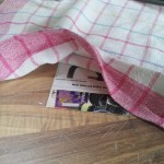
At first export the top and bottom side of your board design as image, and arrange them next to each other. You have to mirror the top layout in order to transfer it in the correct manner onto the PCB later.
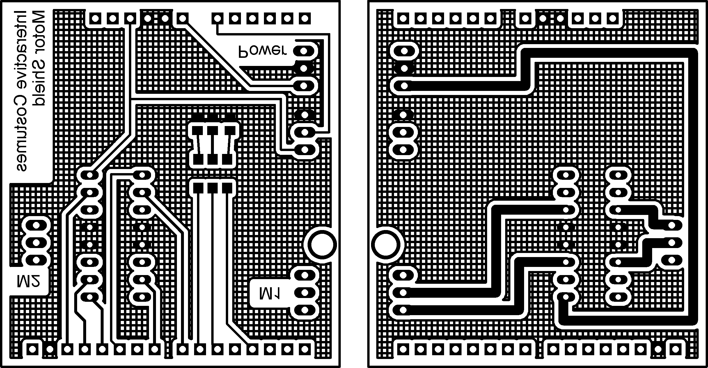
Next you have to print this image with a laser printer on a glossy paper. This prevents the toner from being soaked by the paper completely. It is advisable to print it several times to have some if it doesn’t work the first time.

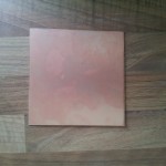
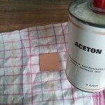
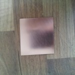
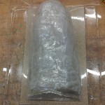
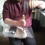
The second preprocessing step is to prepare the circuit board for the transfer. At first cut a piece of circuit board in the dimensions of your layout. Next you have to clean it really good. At first use steel wool for a rough cleaning of the board. After this use acetone to really get rid of all dirt and fat. After this procedure the copper should be shiny like a mirror. During the cleaning and transferring you should wear gloves to ensure the copper stays clean.
Transfer layout
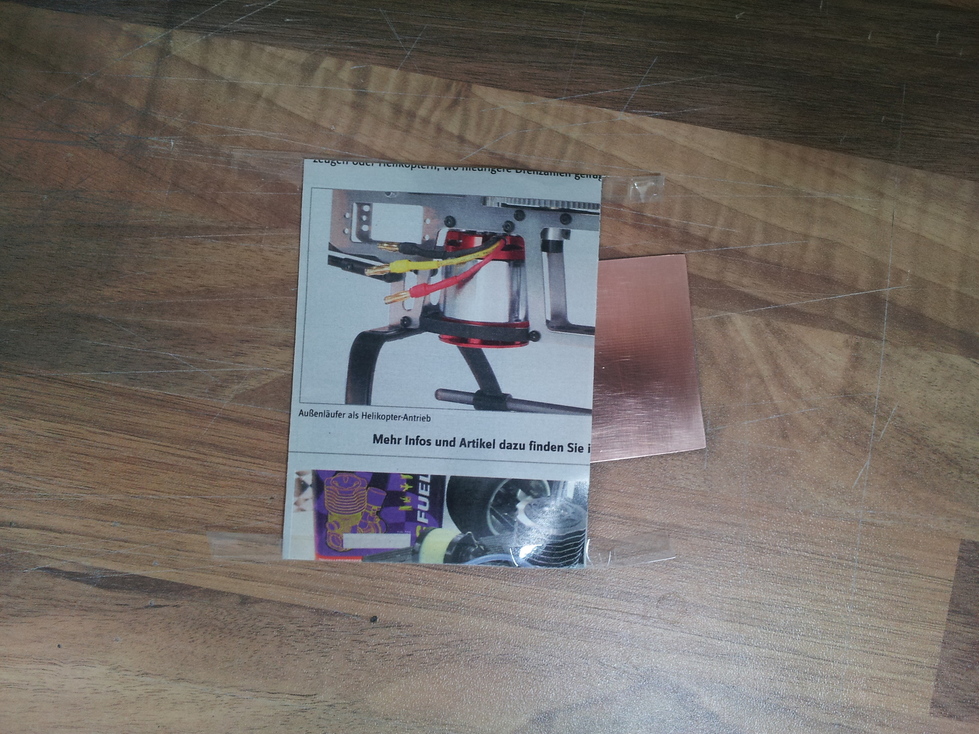
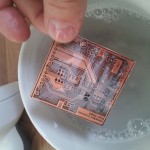
After you have your design on glossy paper and the circuit board is clean, they should come together. Because I have a two-sided layout, I have to ensure that all holes are on the same position for both sides. Therefore, you can build a small bag for the circuit board. Fold the glossy paper with the design so that both sides lie exactly on top of each other. Use duct tape to fix two other sides. Insert your circuit board from the fourth side and place it such that the design borders fit with the circuit board edges.
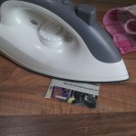
Now you have to transfer the design onto the circuit board. Therefore, you can use an electric iron. It is advisable to put some cotton rag between the electric iron and the paper. Adjust the electric iron to cotton temperature (This may vary with other electric irons). And start ironing the design.
After 5 minutes the toner should be hot enough to stick to the copper. Put the (!HOT!) circuit board in a bowl with cold soap water and wait another 5-10 minutes. Then the catalog paper will dissolve. You can carefully rub over the circuit board to remove the last catalog paper.
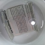
As result, you have a copper board with your design on both sides printed.
Etch
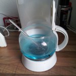
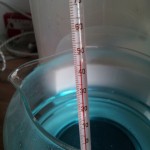
Now comes the interesting part. To etch your layout you need some Sodium Persulfate (NA2S2O8). It should have a temperature around 50°C (not more!). I use the hot plate of an old coffee maker to heat the etchant. Be careful, the etchant will make holes in fabrics, so don’t drip at your clothes (and be careful with your skin as well).
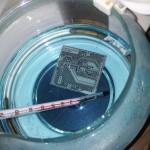
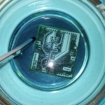
After some minutes you can see how the copper disappears from the circuit board. The toner prevents the design part from being removed by the etchant.
 Next you have to remove the toner. Therefore, you can use again acetone.
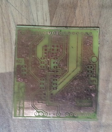
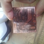
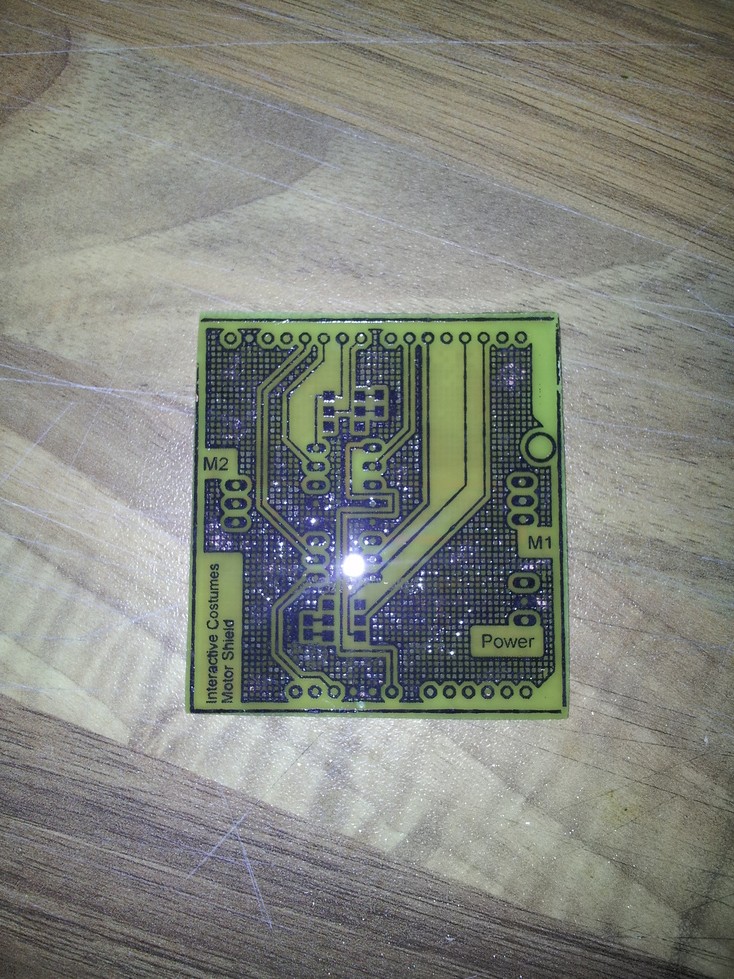
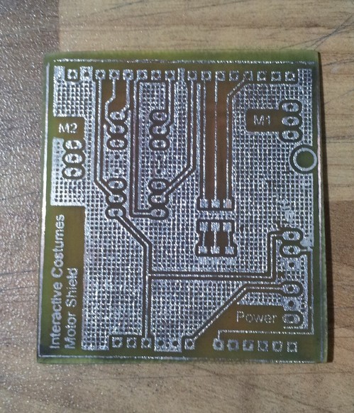
Now your circuit is on the circuit board!
Postprocessing
To prevent the copper from oxidating it is necessary to tin-coat it. For this purpose I use Rosol 3 which is available in the hardware store.
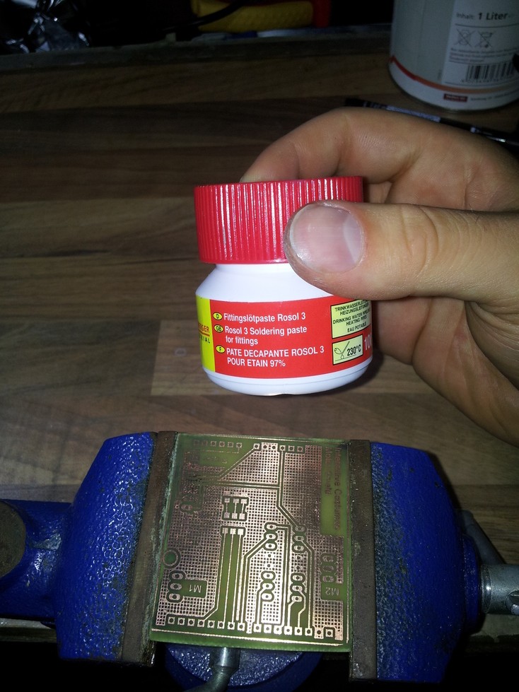
Just brush a thin layer of the Rosol 3 onto the circuit board.
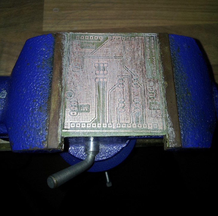
Next use a heat gun to heat the tin until it starts to melt.
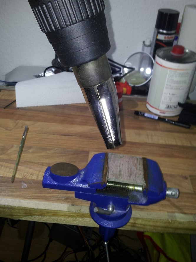
Your circuit board is now silver and protected against oxidation.
Drill
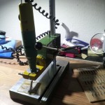
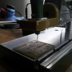
To assemble the parts to your circuit board you need to drill all the holes. I use a small Proxxon drill with drill rig. Connectors need holes with a diameter of 1.0mm, DIP packages need 0.8mm.
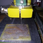
After this step you are nearly finished!

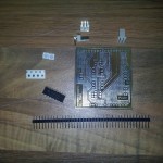
Assemble
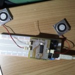
Last but not least you have to assemble your parts and test your circuit .
Final Exhibition – Summaery – Open Lab Night
Dear All,
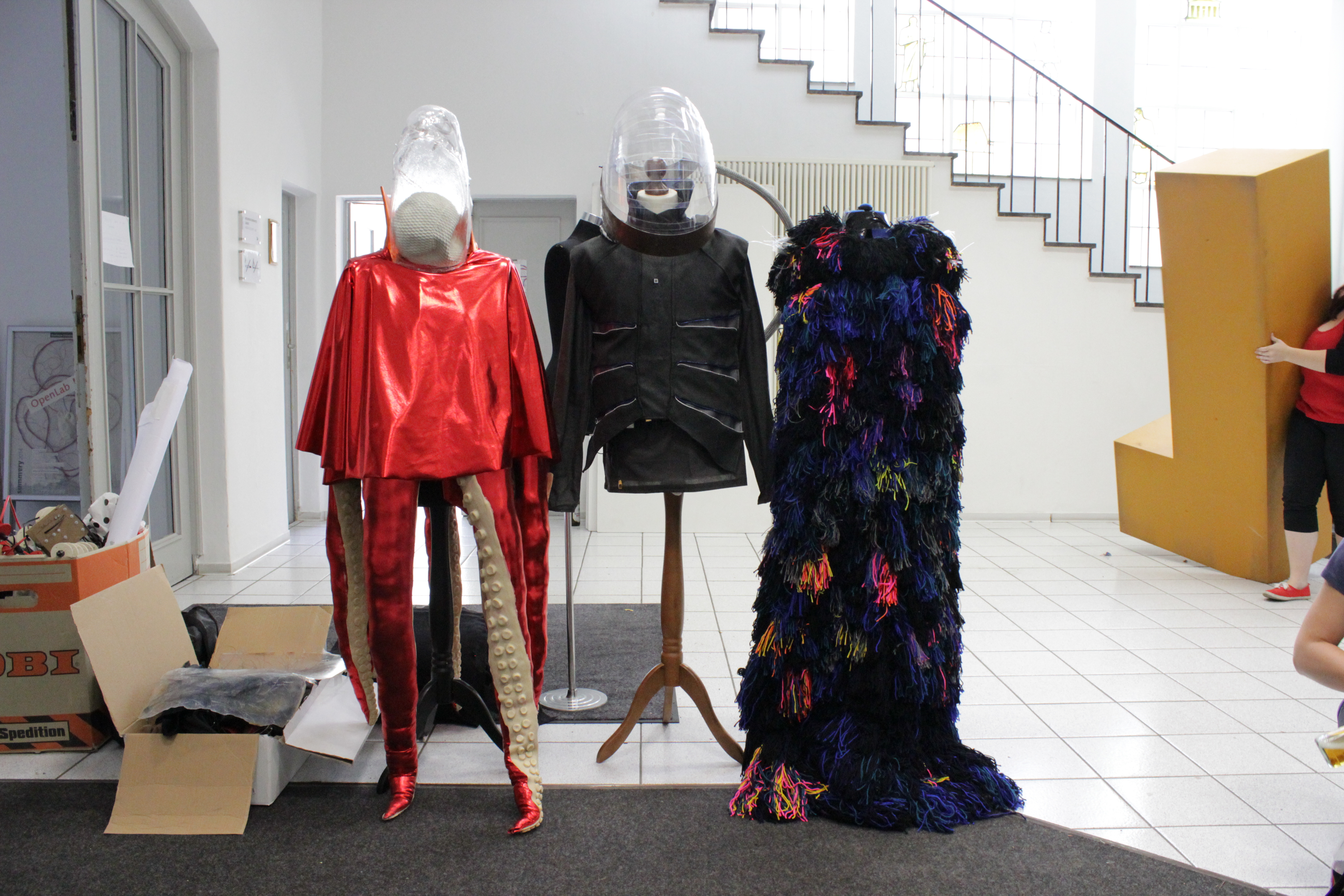
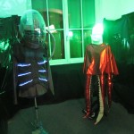
we present to you: our final exhibition!
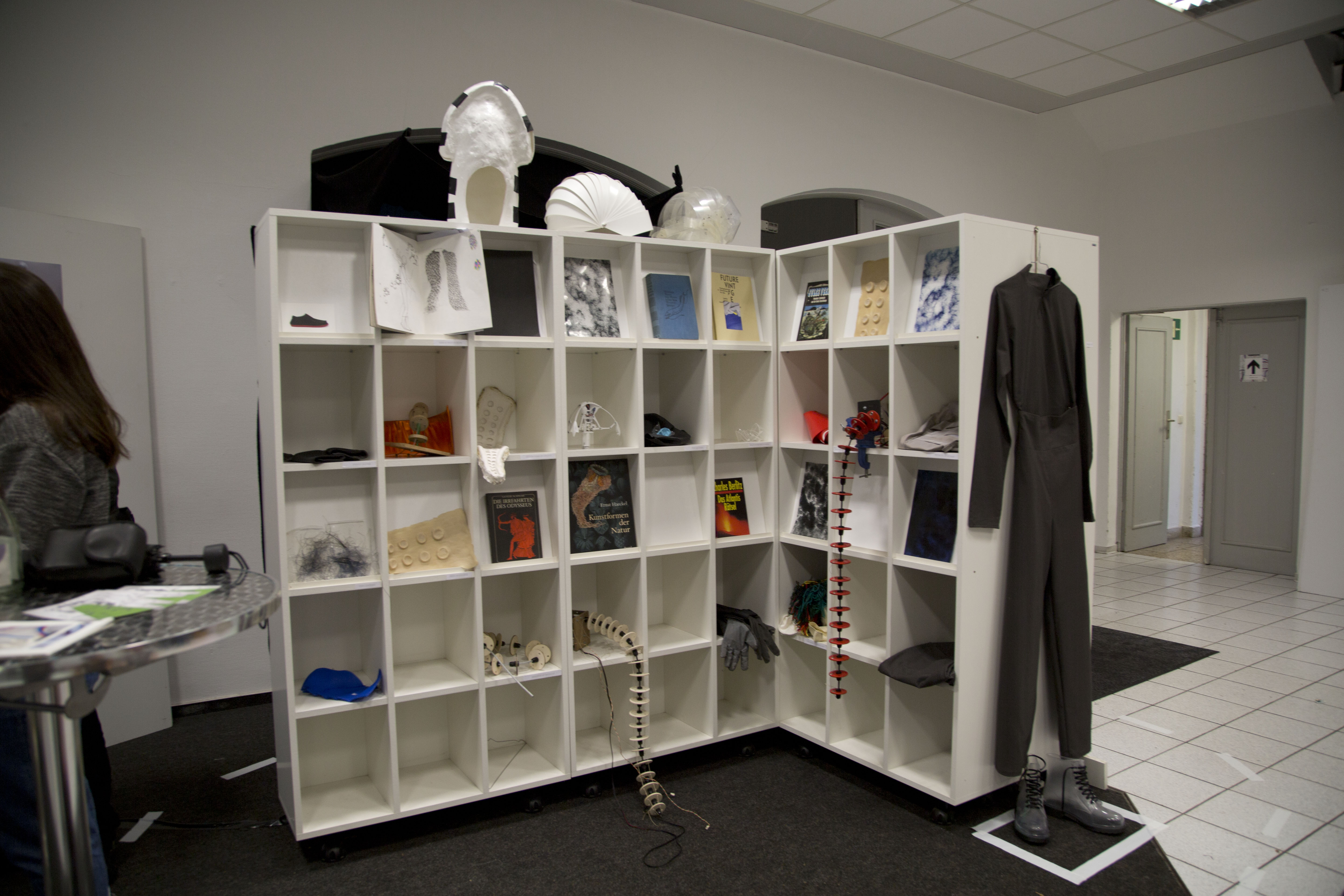
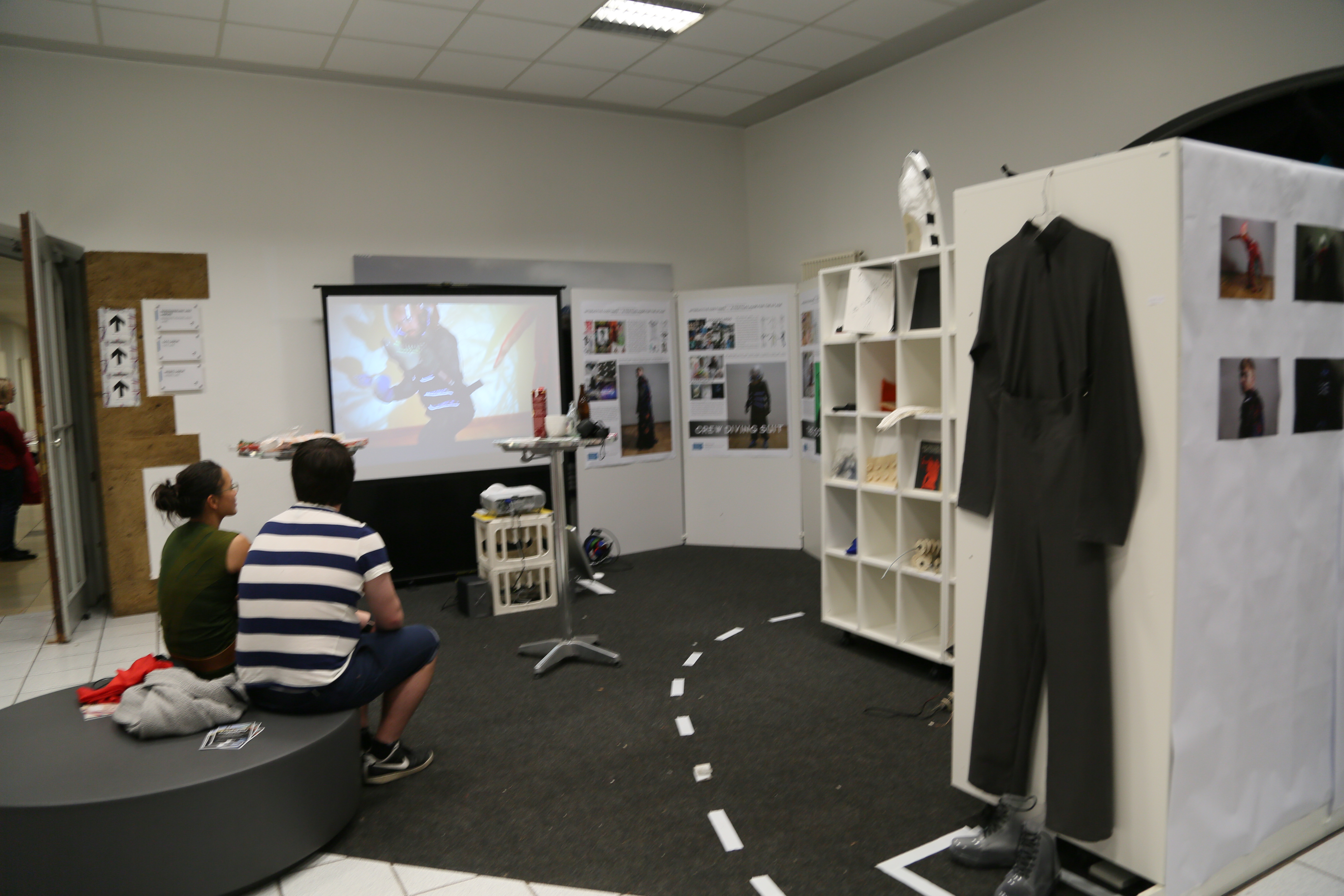
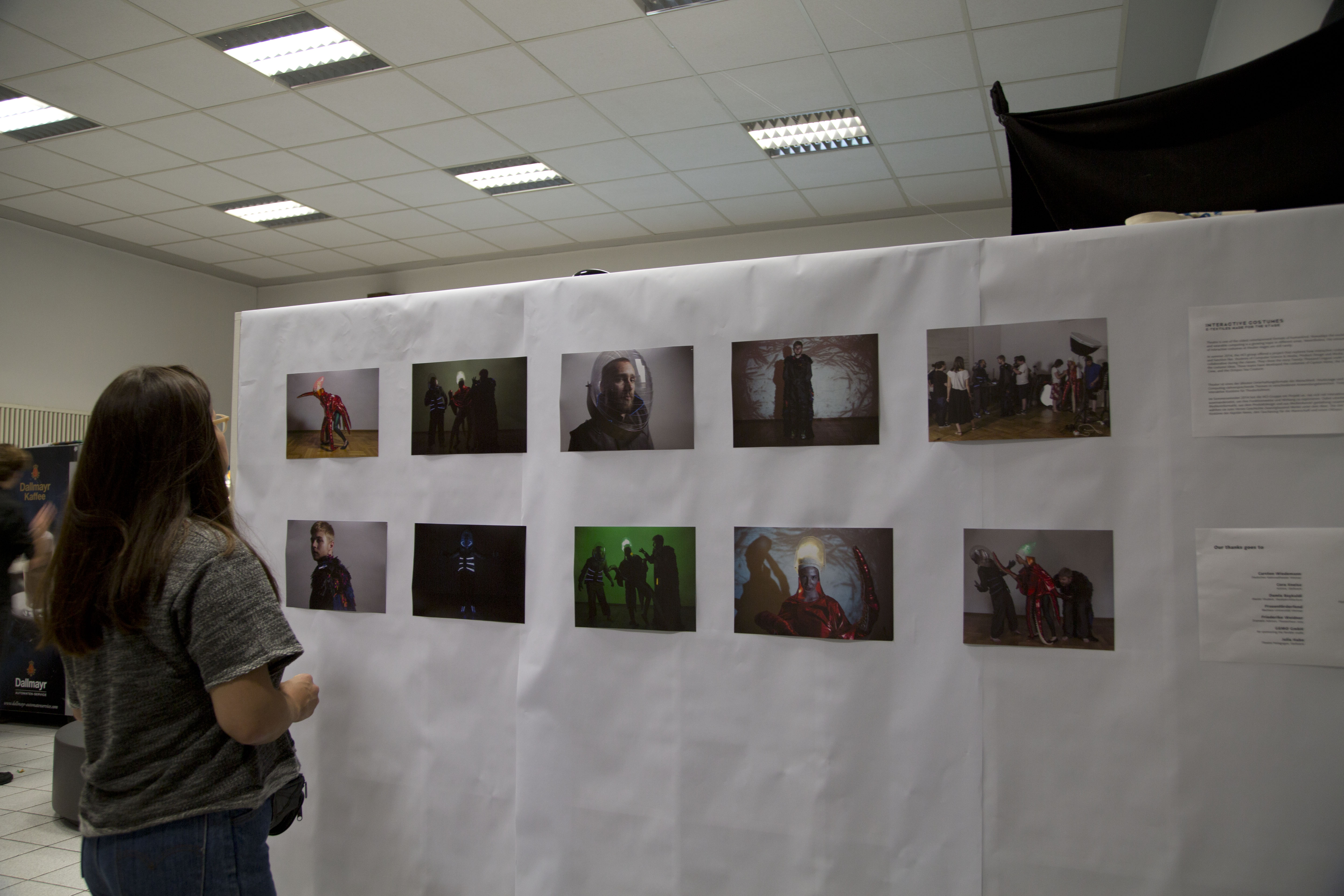
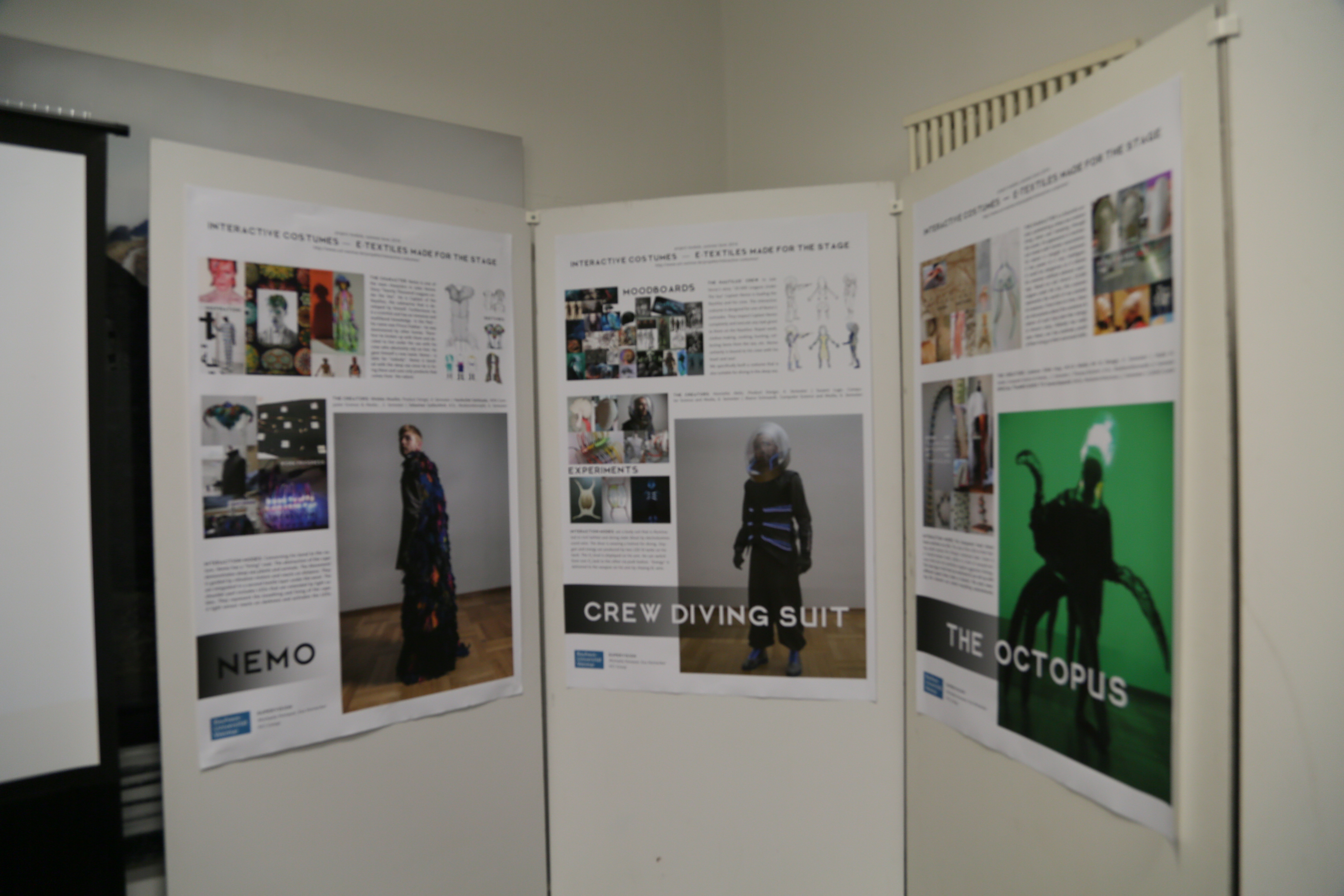
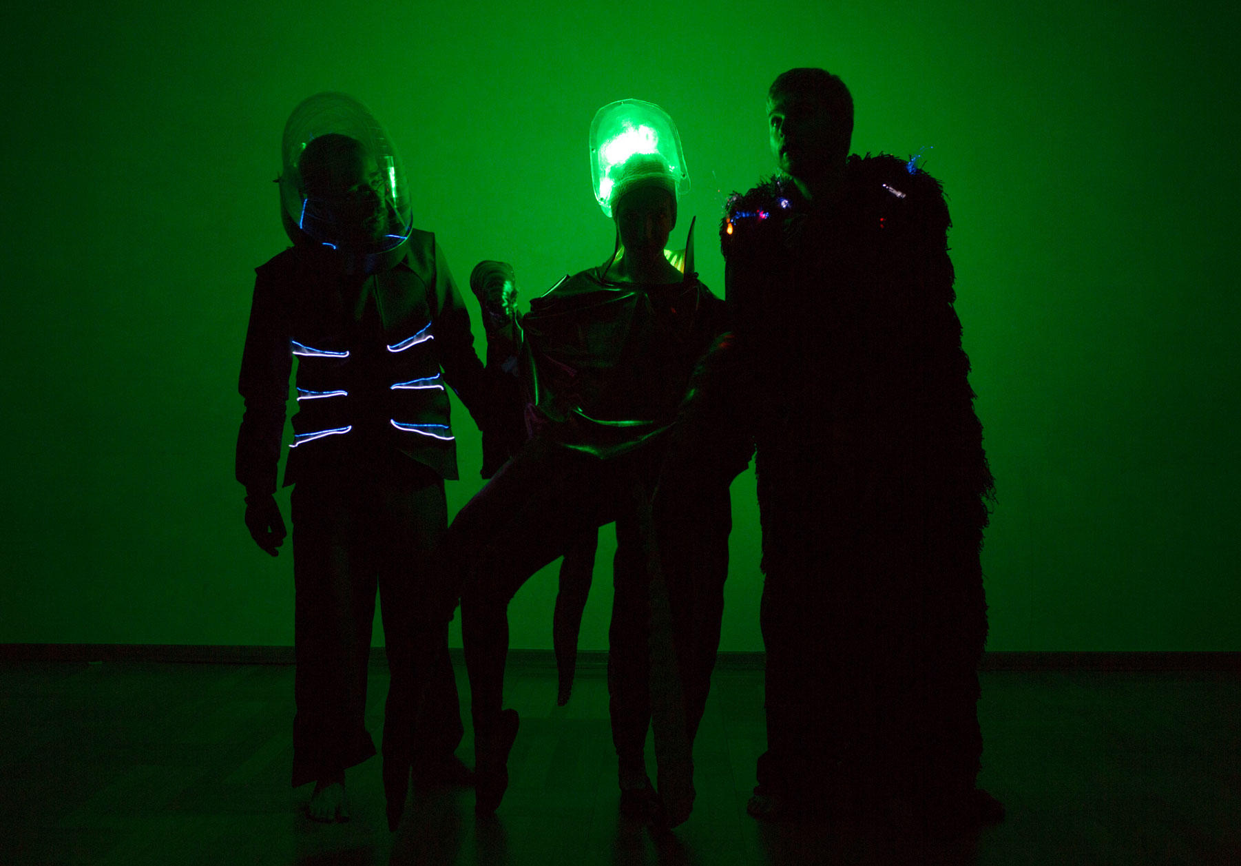
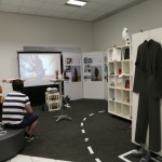
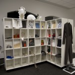
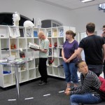
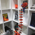
The designers always come up with these crazy ideas that are a lot of effort. I guess in the end it was worth it. We presented the project – costumes, mock- ups, prototypes, pictures and movie in the entrance hall of Bauhausstraße 11. We tried to make it an overall experience so that the visitor understands the project´s goal. The visitor had to pass shelves filled with prototypes and inspirational material. The video that was shot during the design acting weekend gave a perfect introduction to our project´s idea and storyline.
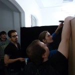
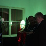
We created a small dark nook to present the costumes with their interactive properties. The visitor really had to enter a “different” world – the Nautilus perhaps?
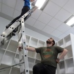
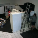
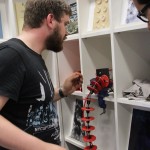
See here some impressions of set up and opening of our successful exhibition!


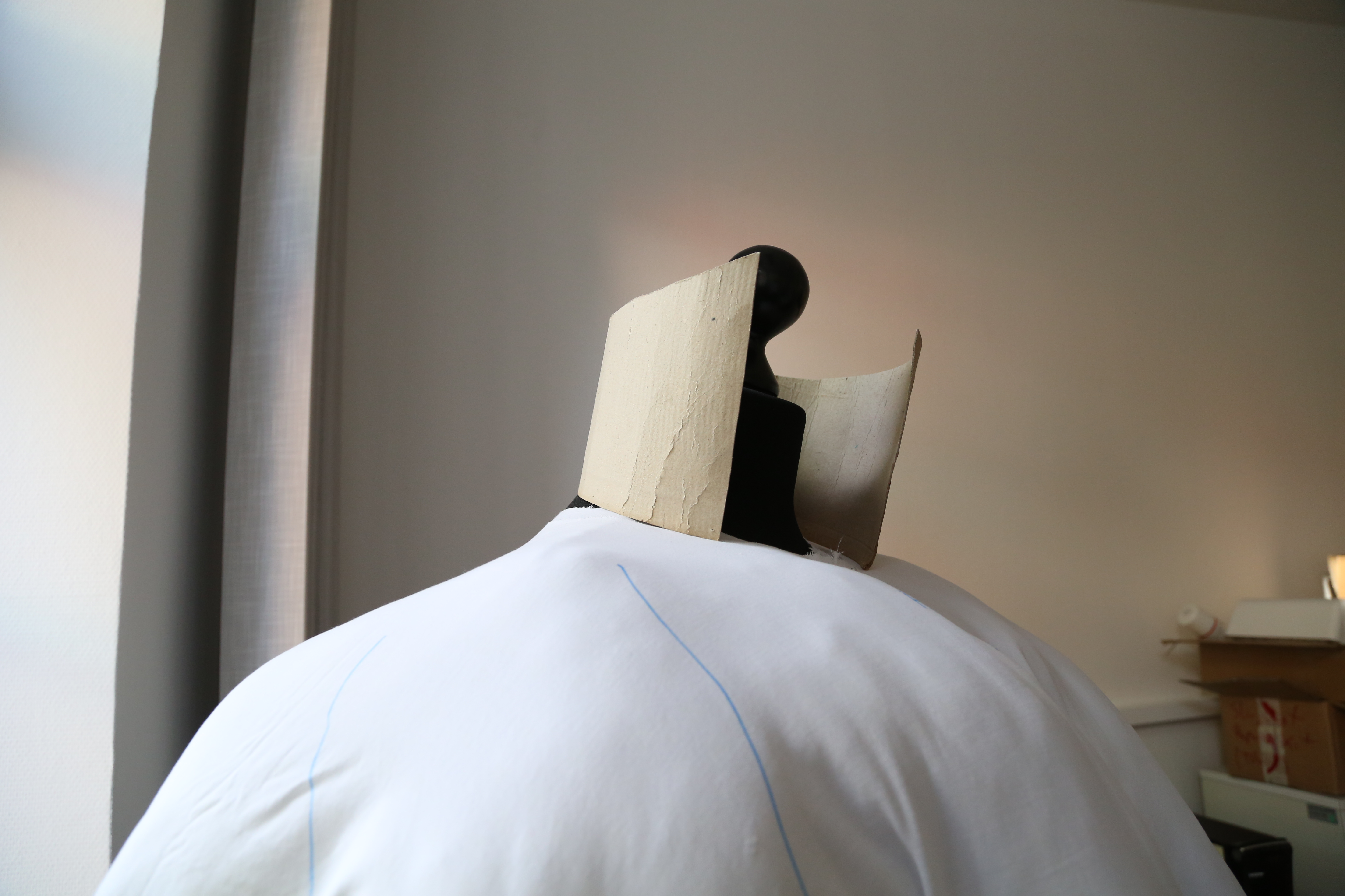
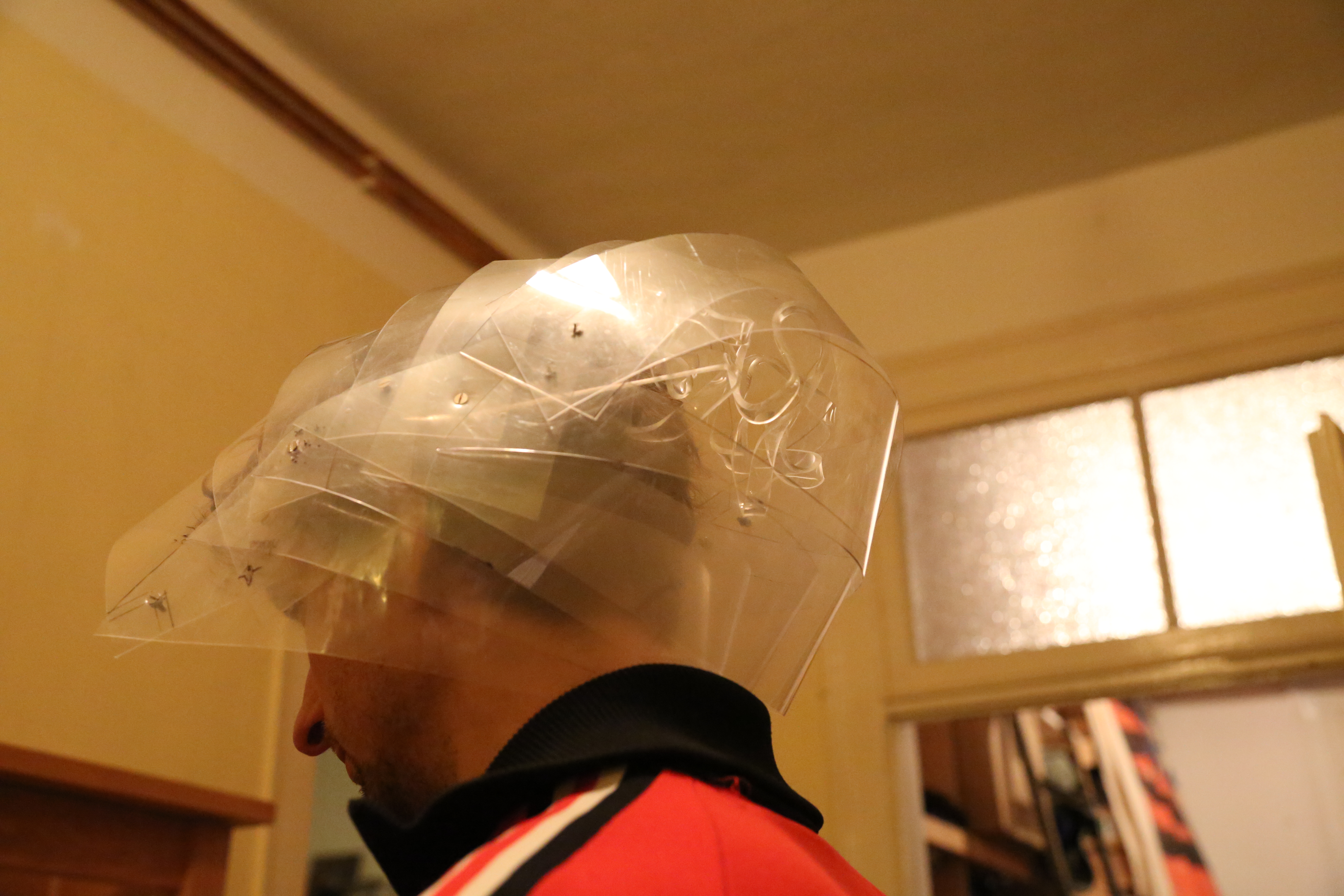
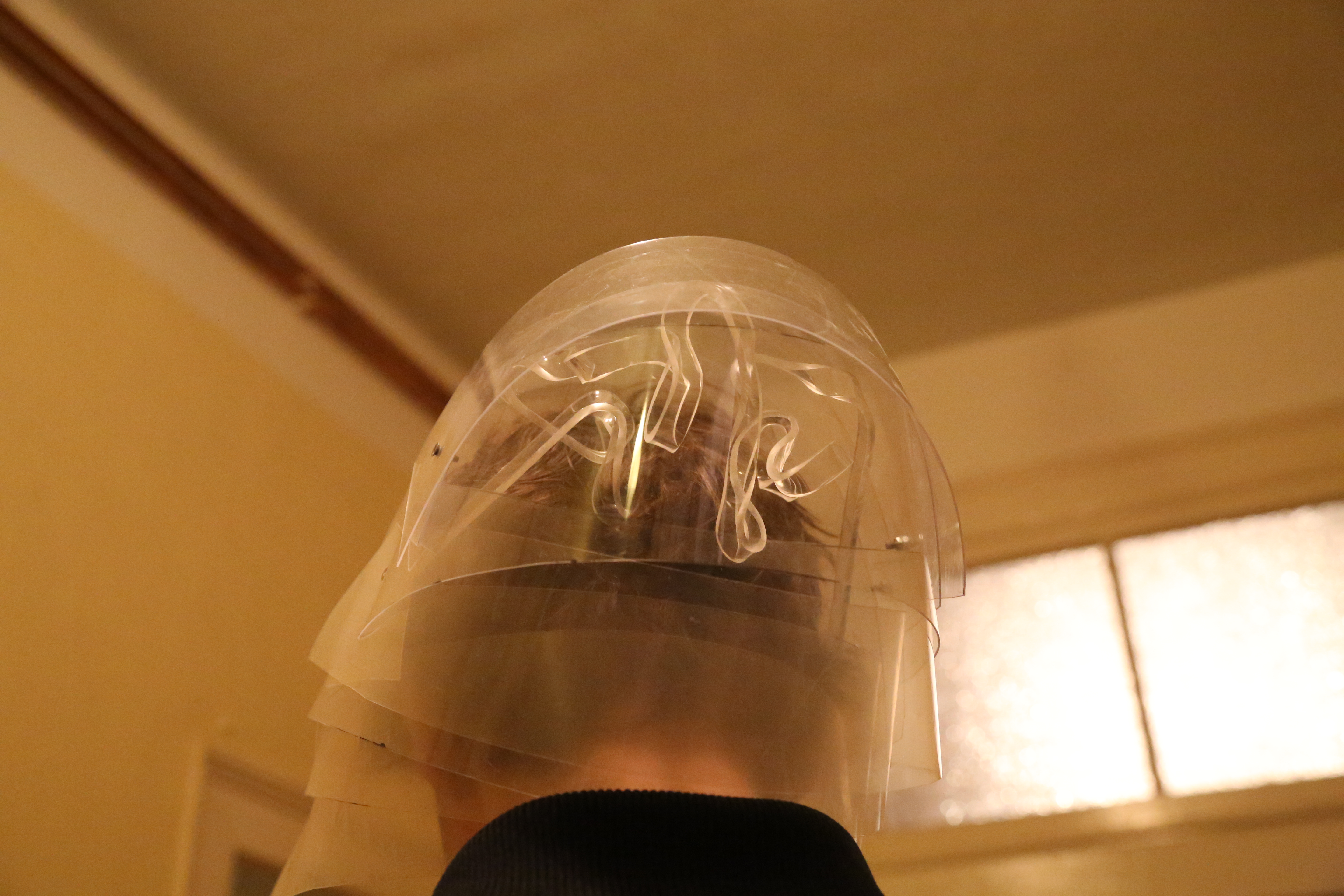
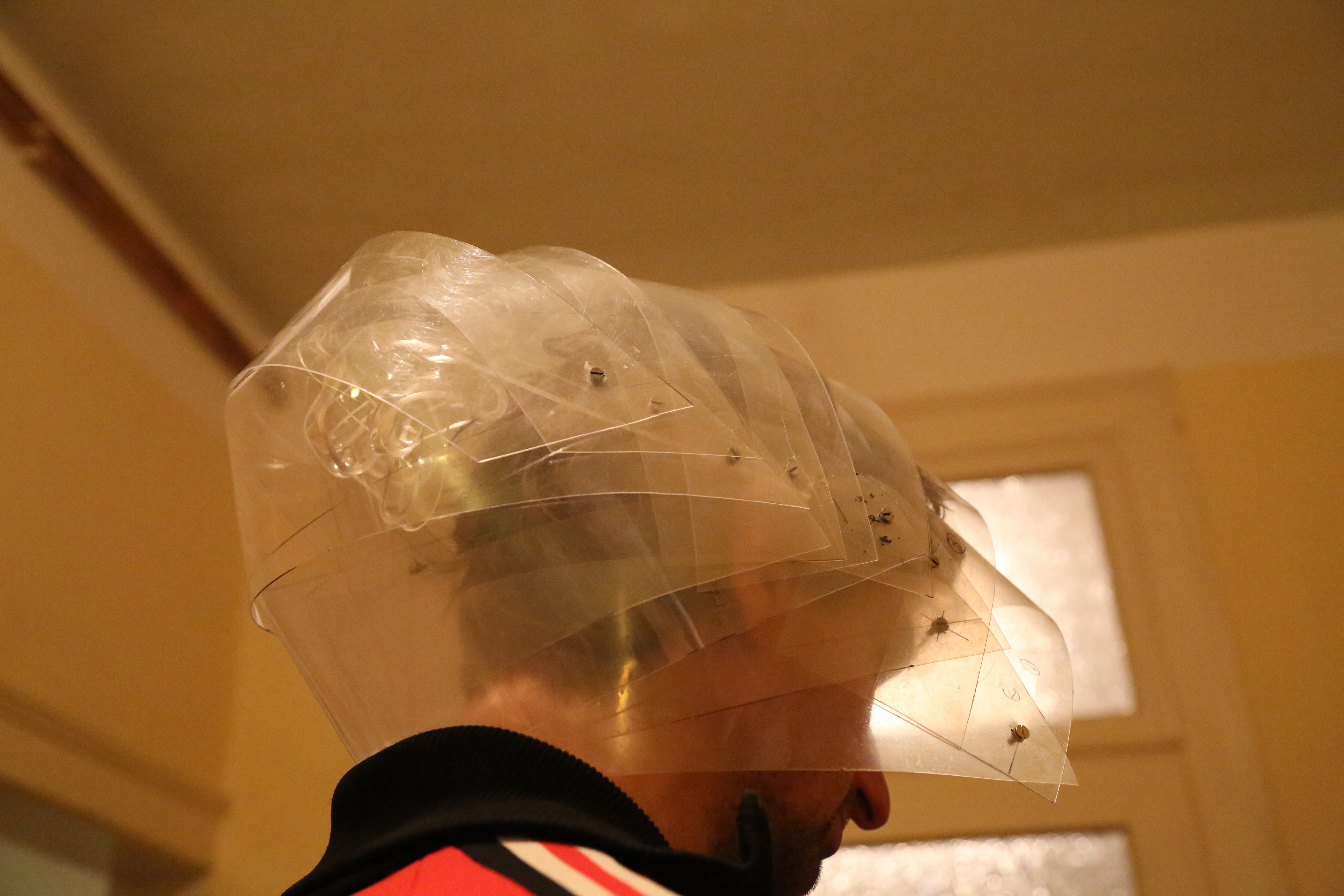
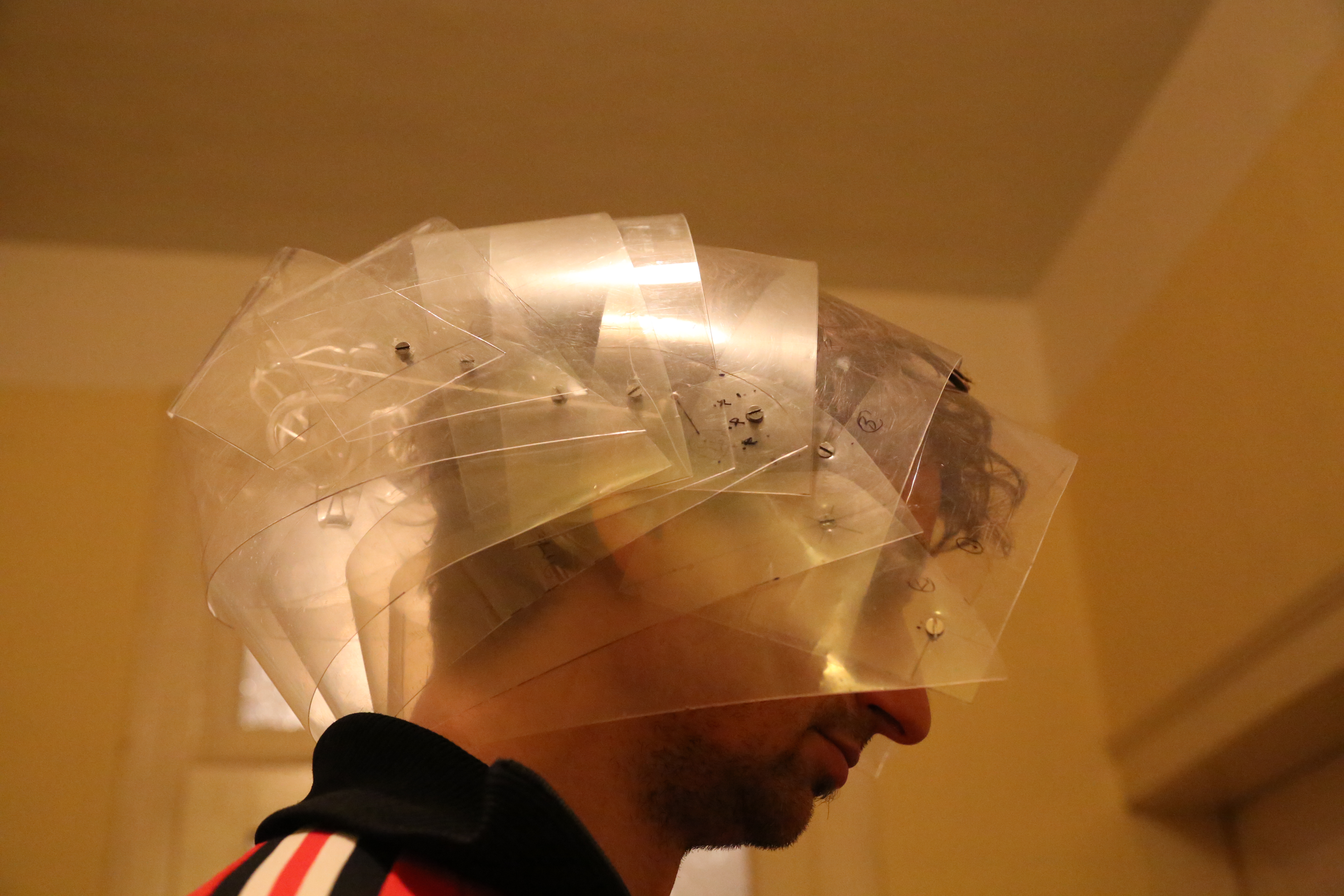
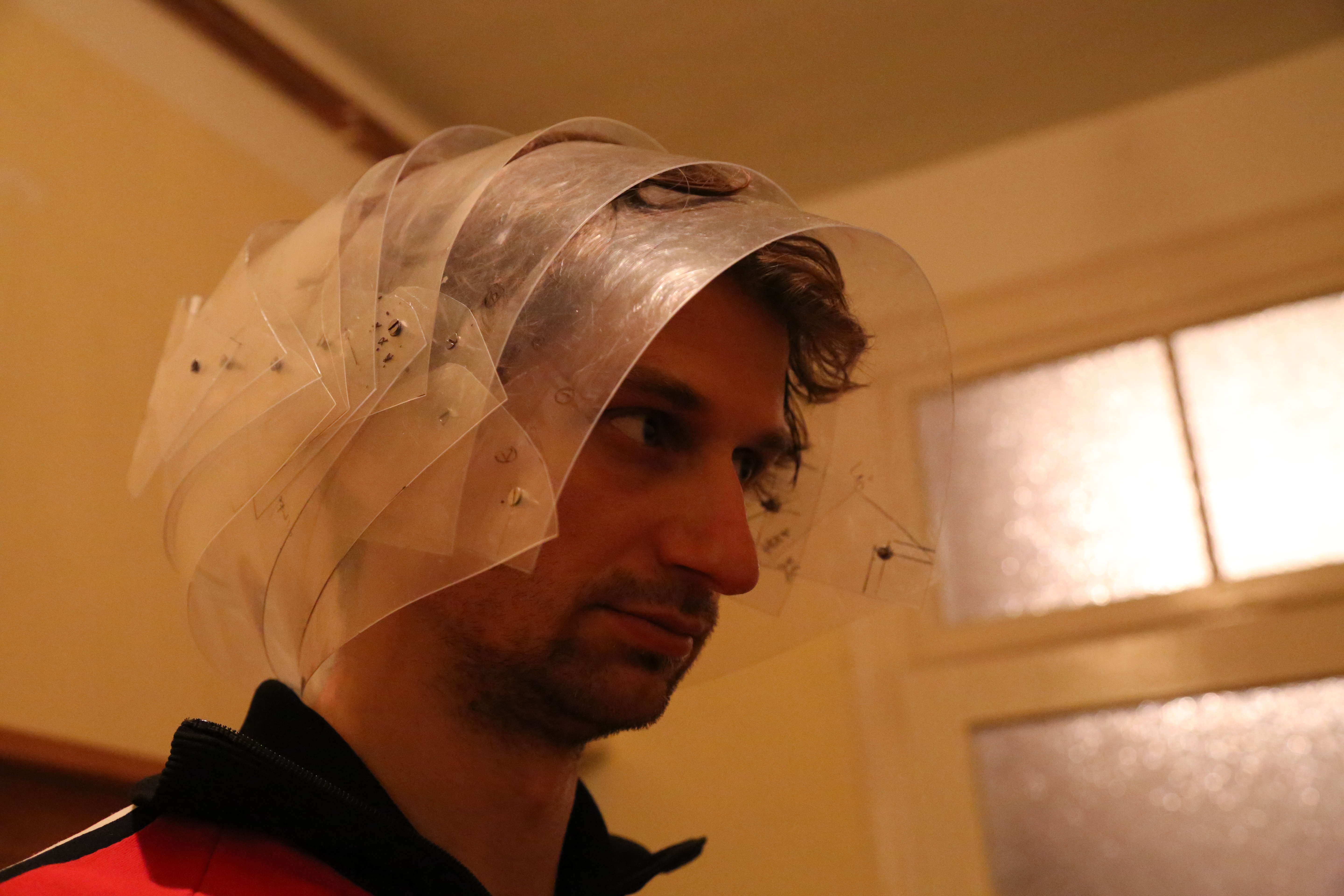
New Head
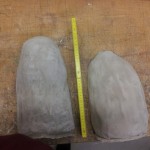
Creating the Vivak head
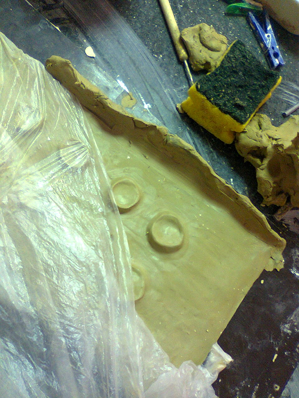
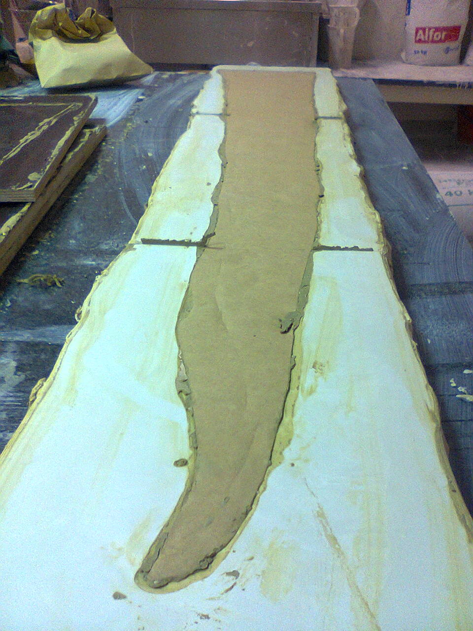
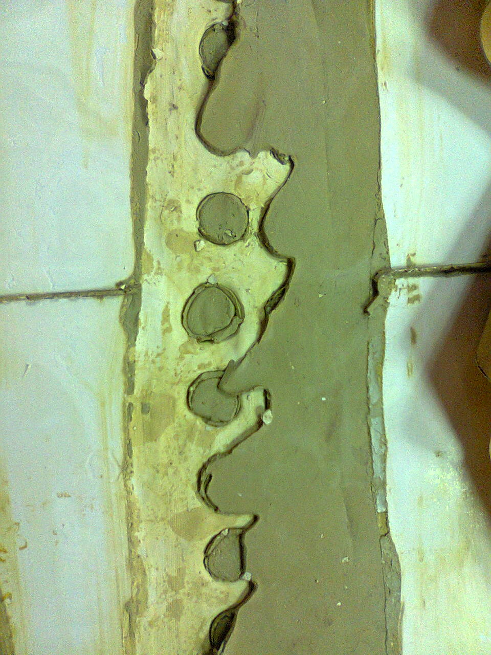
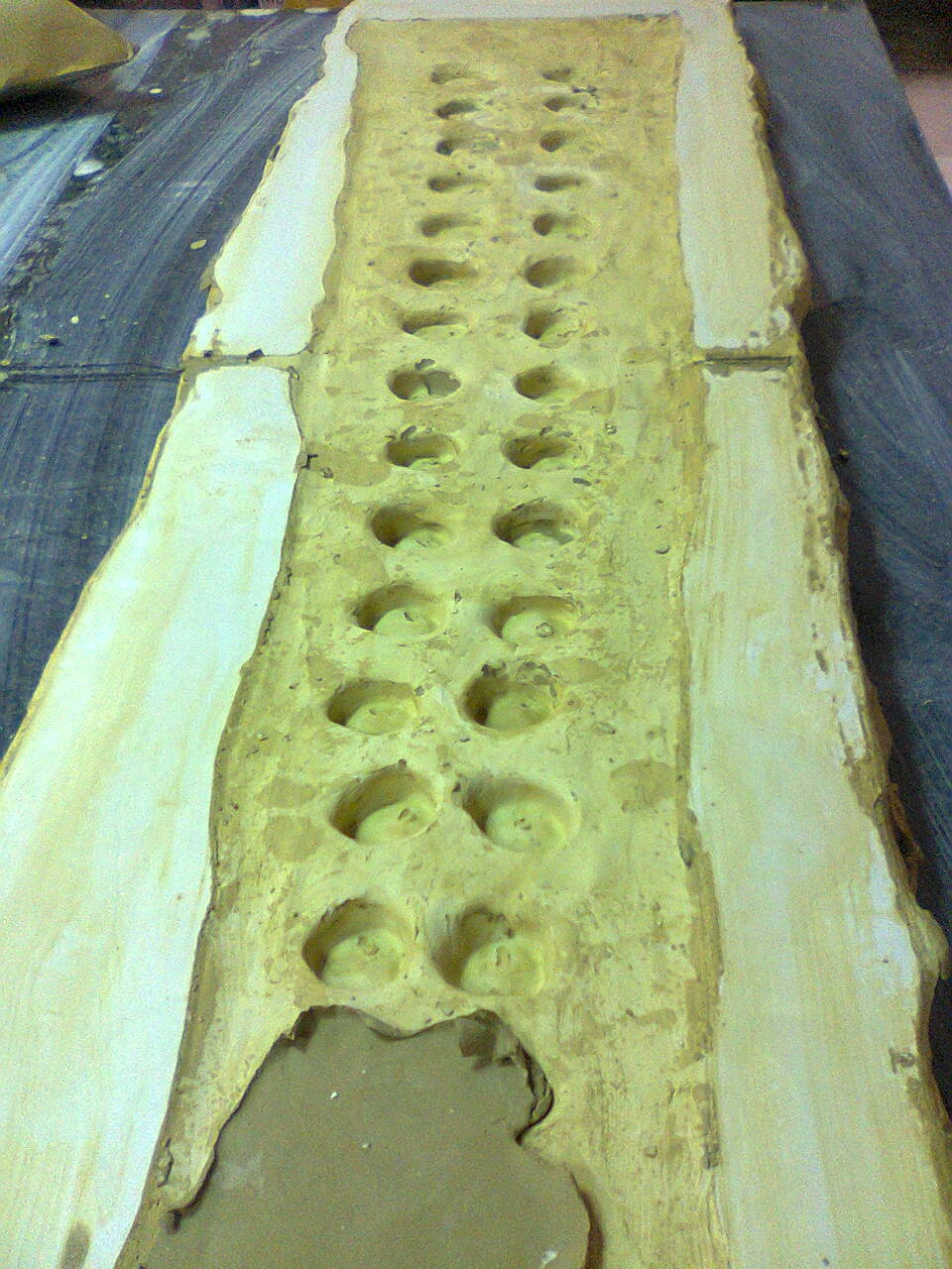
The head form is made of clay


The Vivak is heated to 180°C, then the form is pressed against it. At the end the machine vacuums the head to get the correct form.
Here is a video of the deep-drawing process
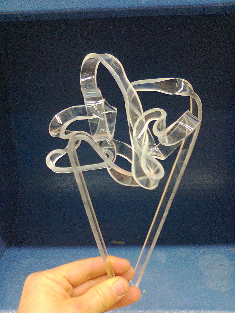
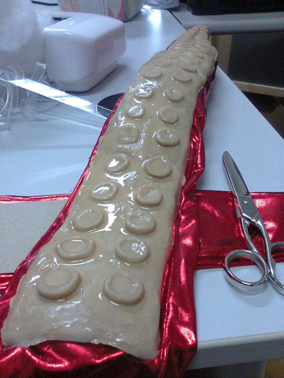
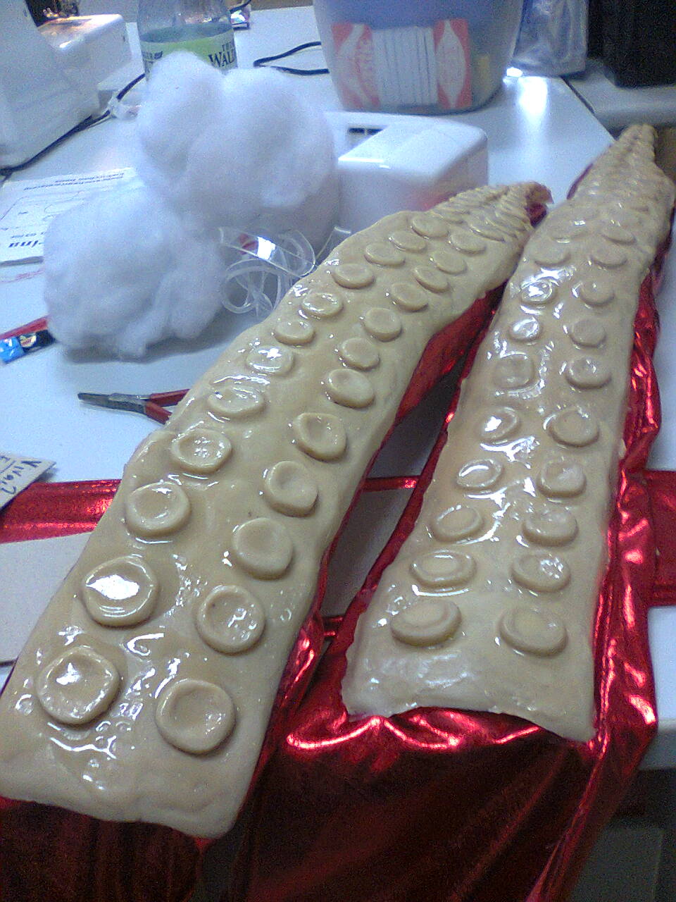
Octopus Costum and Helm
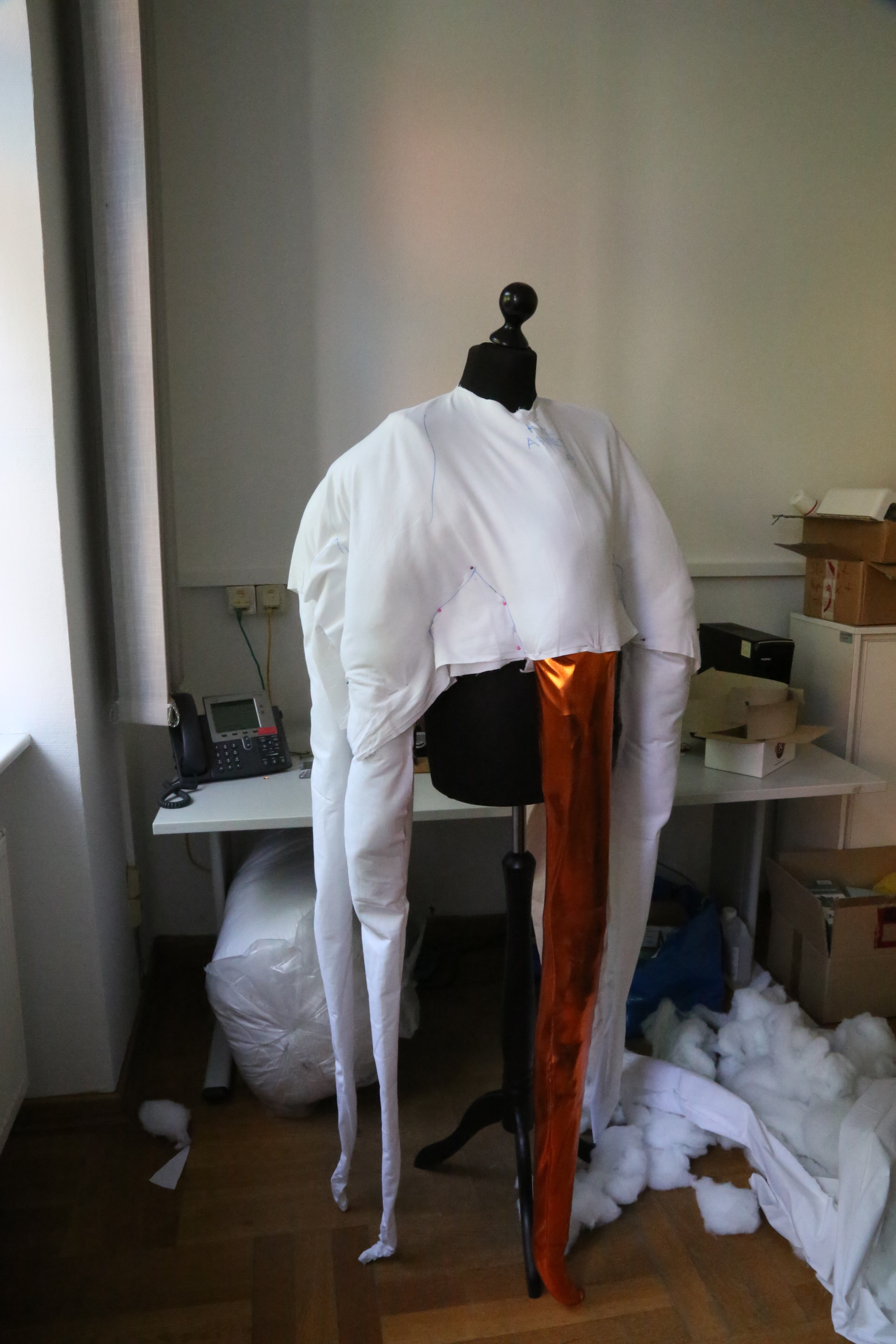
First Prototype of Costum
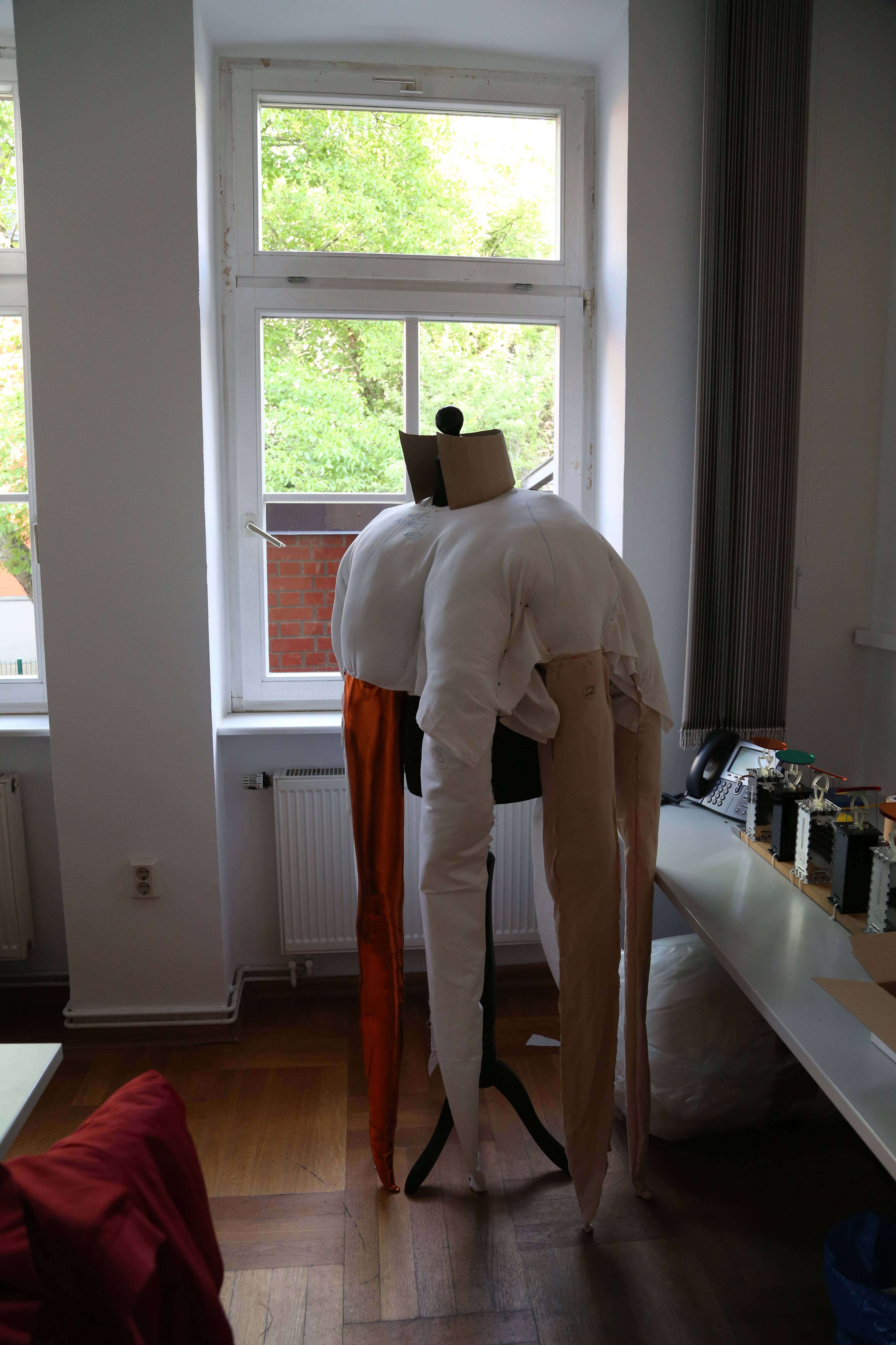

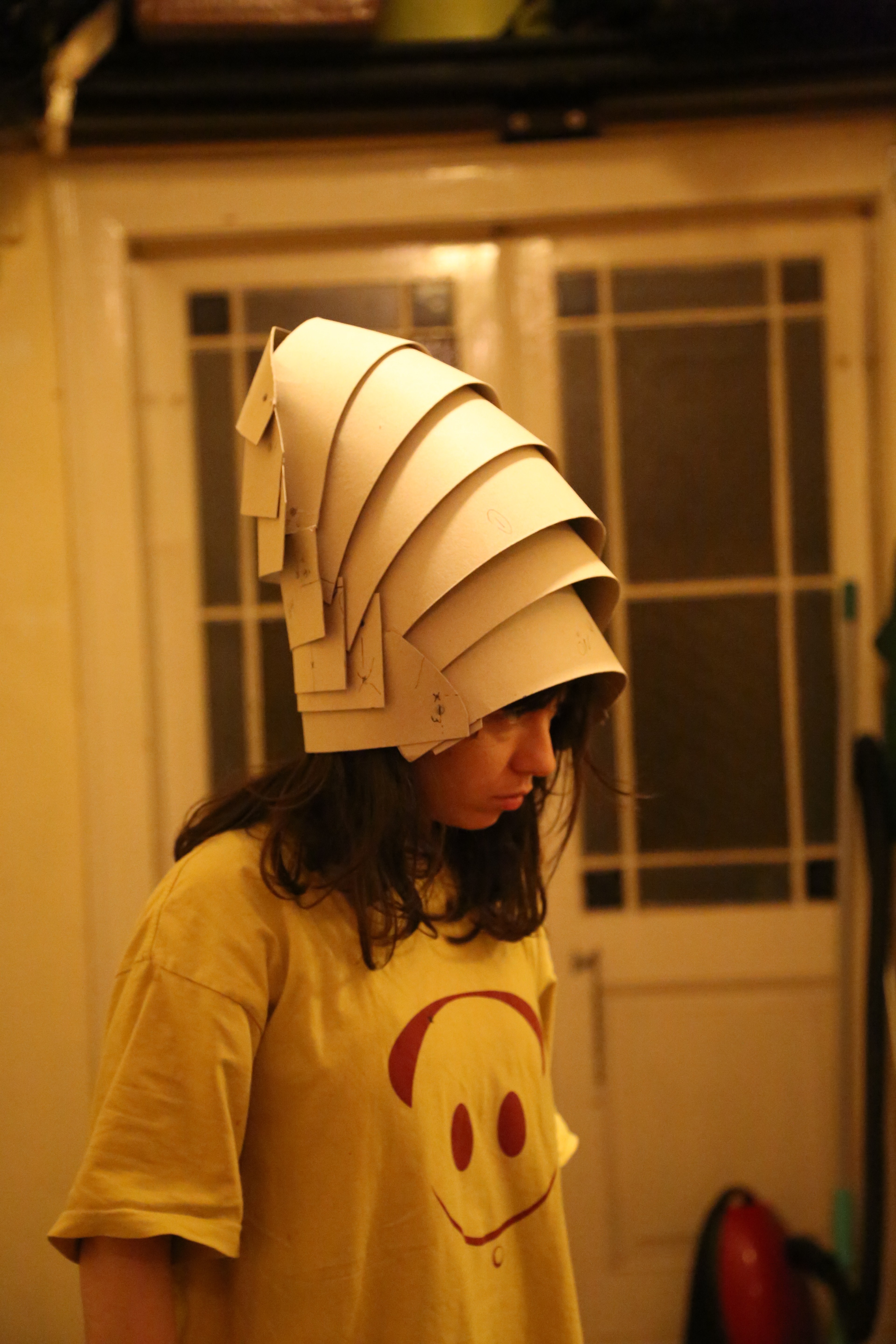
On the Prograss

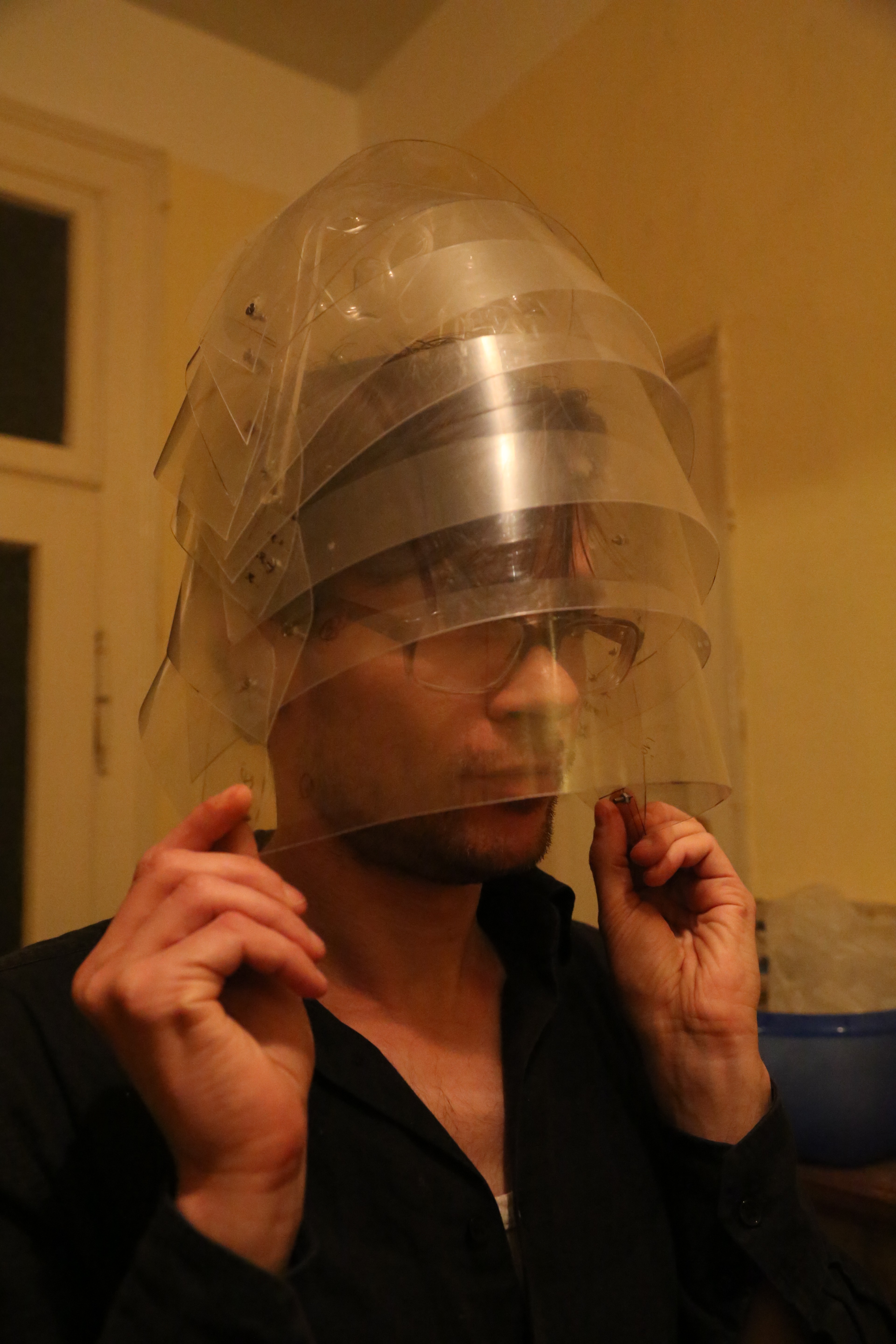
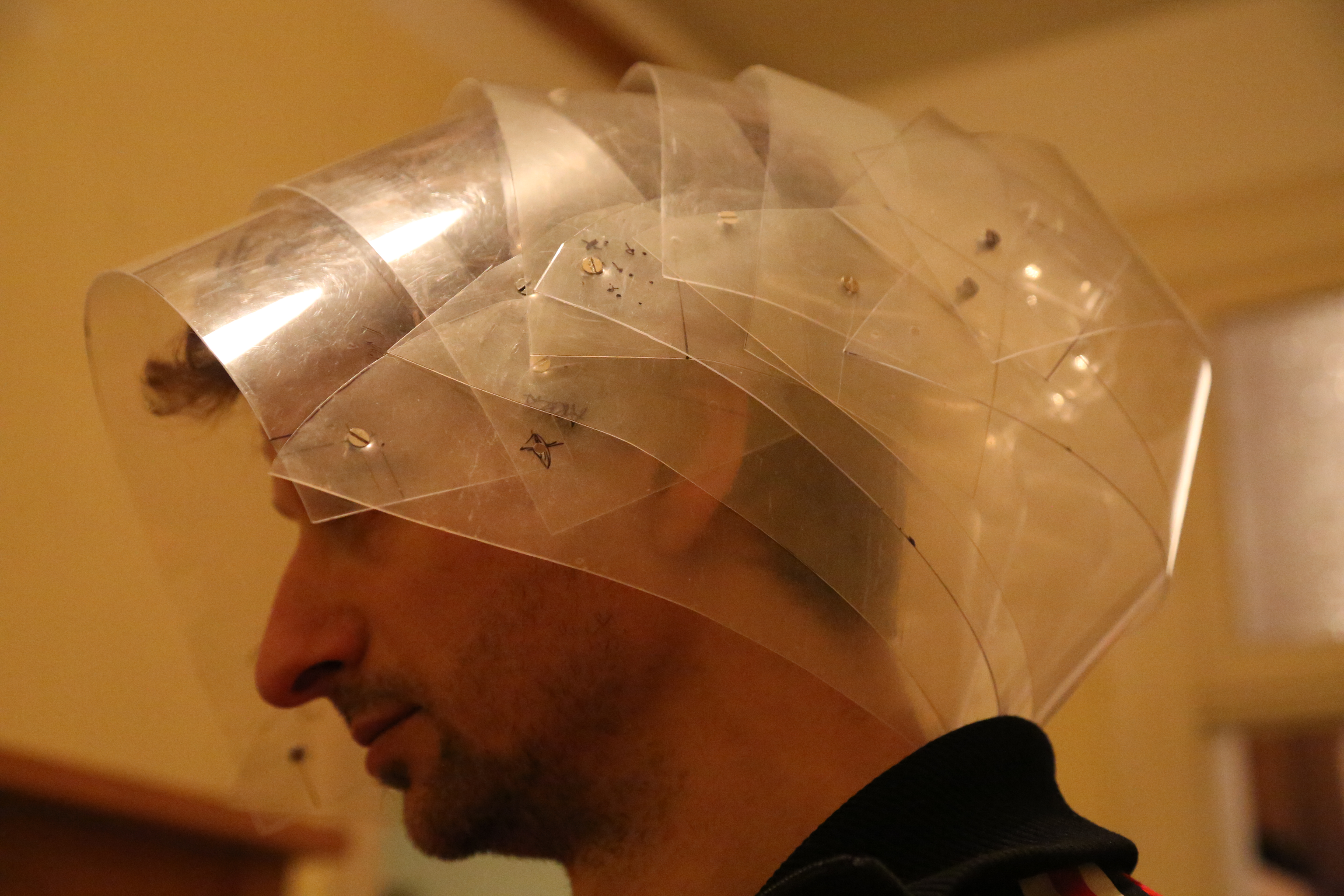
Second Head Prototype with Vivac
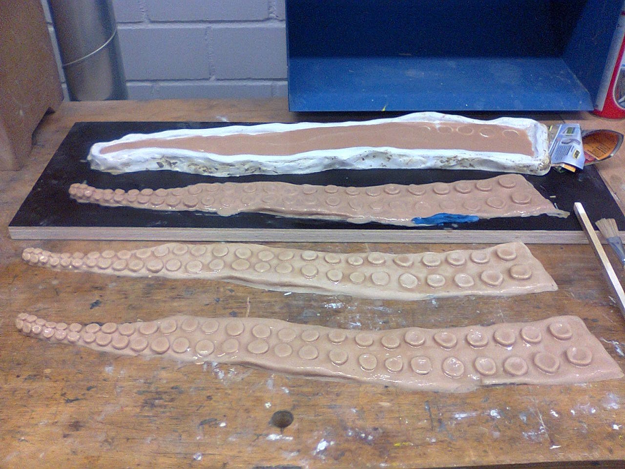
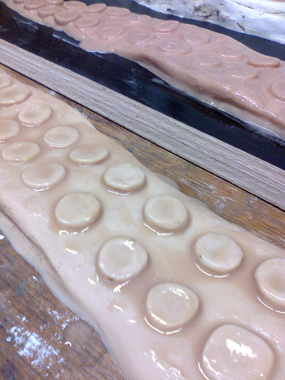
Model for Legs
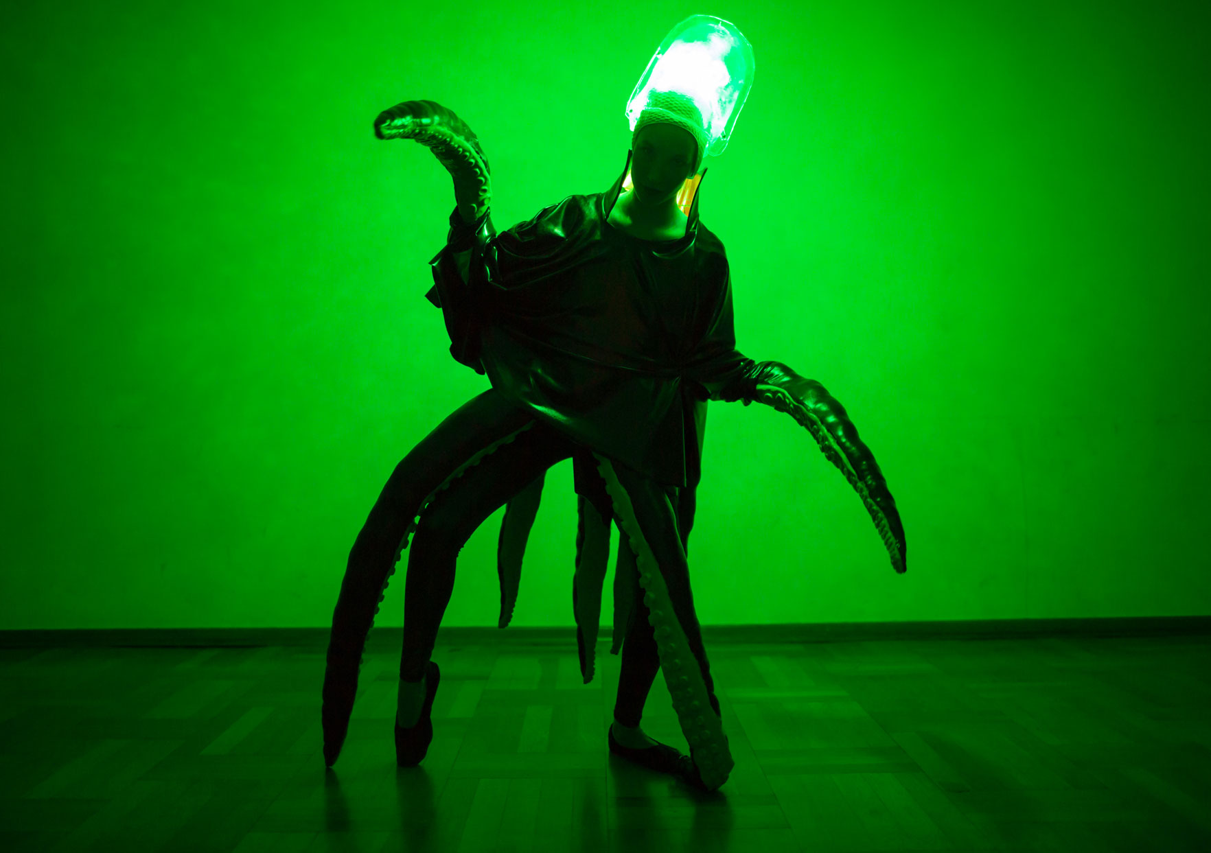
For LED Light, It will come inside of the Head and give shape LED light
Long version of 2. Model for moving Part of Legs
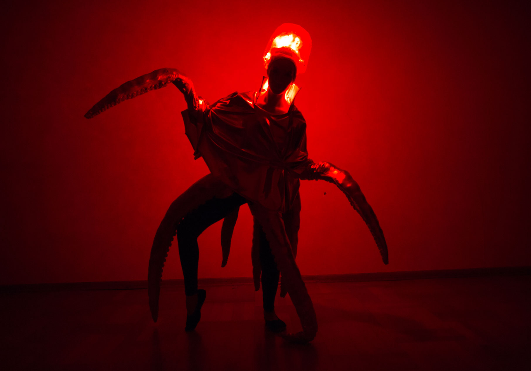
Bringing parts together

It’s Alive !
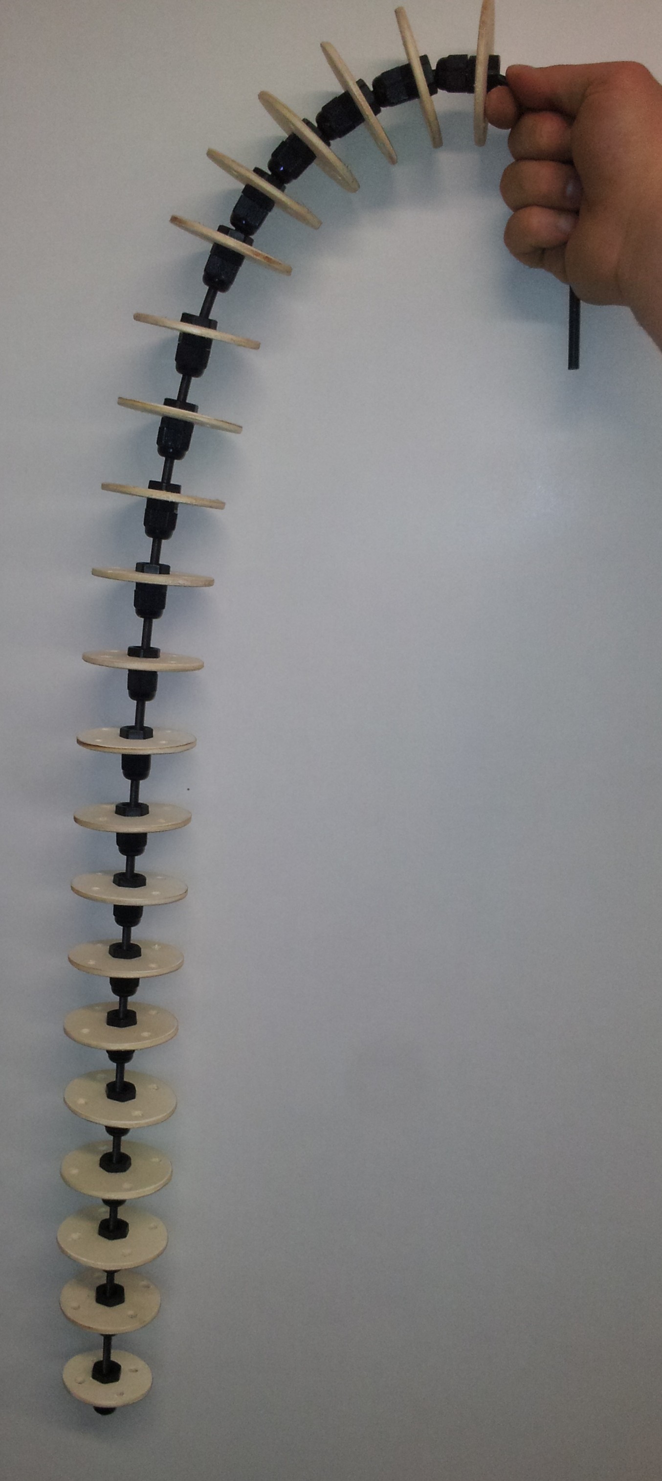
Building your own tentacle
So if you now are interested in how to build your own movable tentacle, I will explain the steps to realize it. This tentacle can be move in two directions ( so along one axis). But for more complex movements the construction stays the same. Only the motor controlling gets more complex to handle more axes.
Materials:
- plywood ( not thicker than 4 mm)
- some cable gland screws (I used some from 3 mm to 6.5 mm sealing scope)
- a flexible shaft (or some thick steel cable)
- some strong threads (these ones are made from aramid fibre)
Tools:
- hole cutters (68 mm, 62 mm, 58 mm)
- dill machine and different drills
- scissor
- screw wench for the cable gland screws
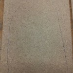
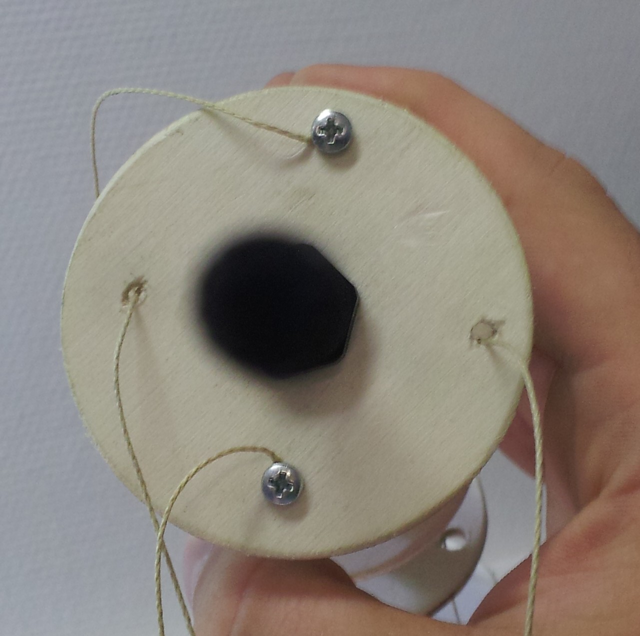
Step 1: The wooden disks
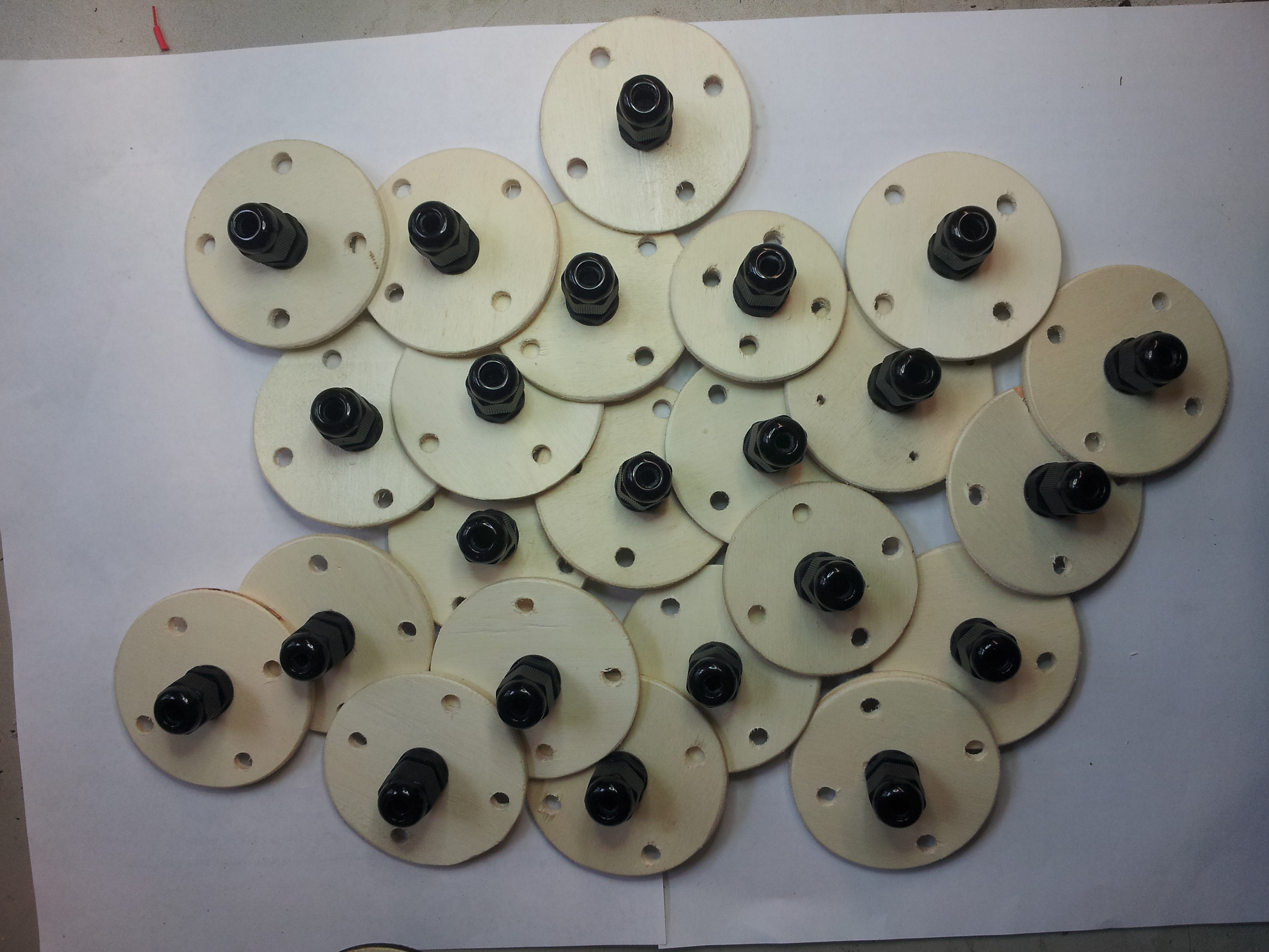
At first you need some vertebrae. Therefore you cut 19 disks with a diameter of 68 mm from the pywood. For the tip of the tentacle you can use one wooden disk with 62 mm and one with 58 mm to indicate the end.
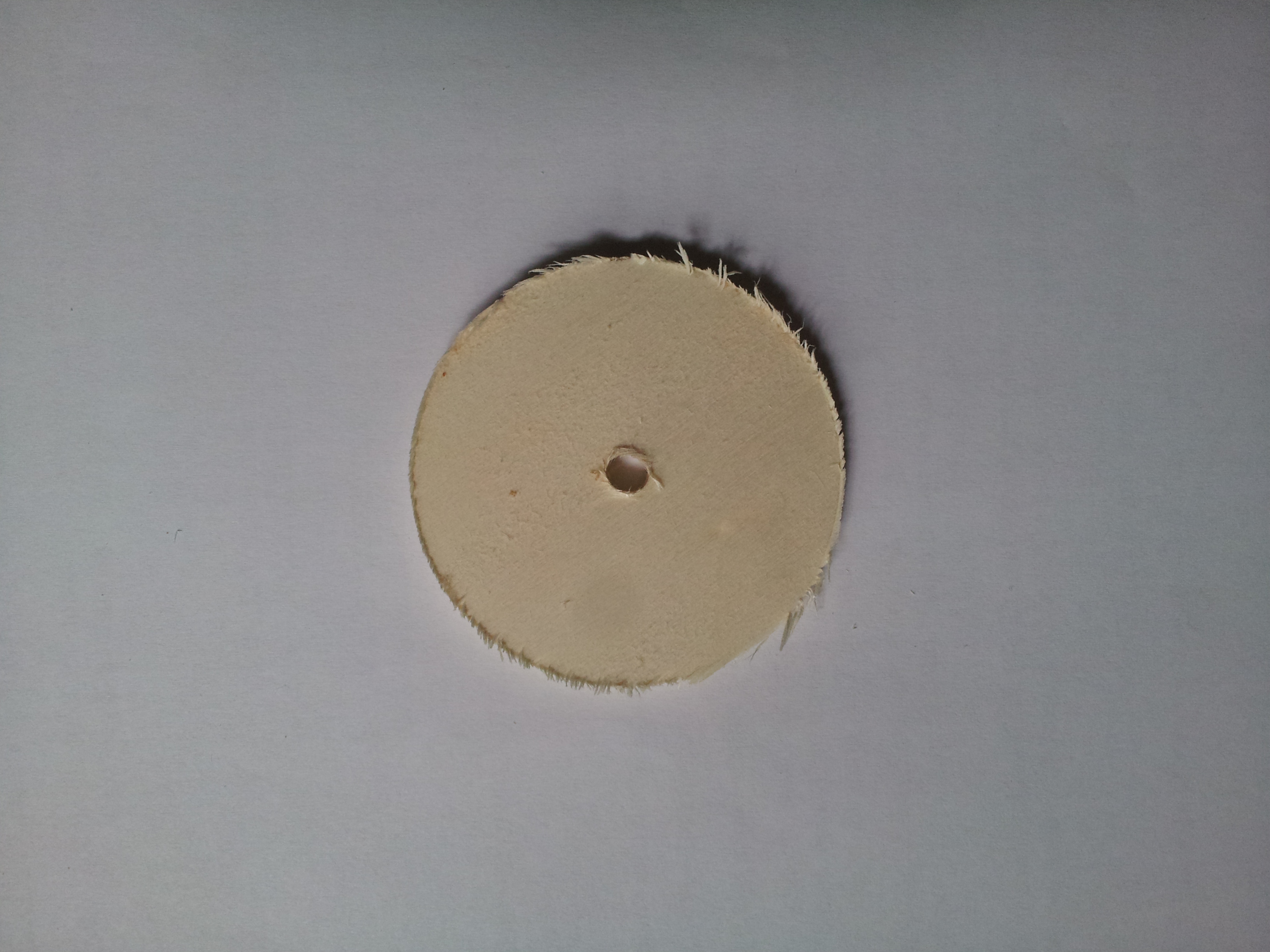
As you can see, after you cut the disk you have to sand it to smooth the edges. Furthermore the hole in the middle of disk which is created by the hole cutter, has to be expanded so that the cable gland screws fit in. Here I used screws with an M12 winding. The result of the sanding and drilling can be seen below.
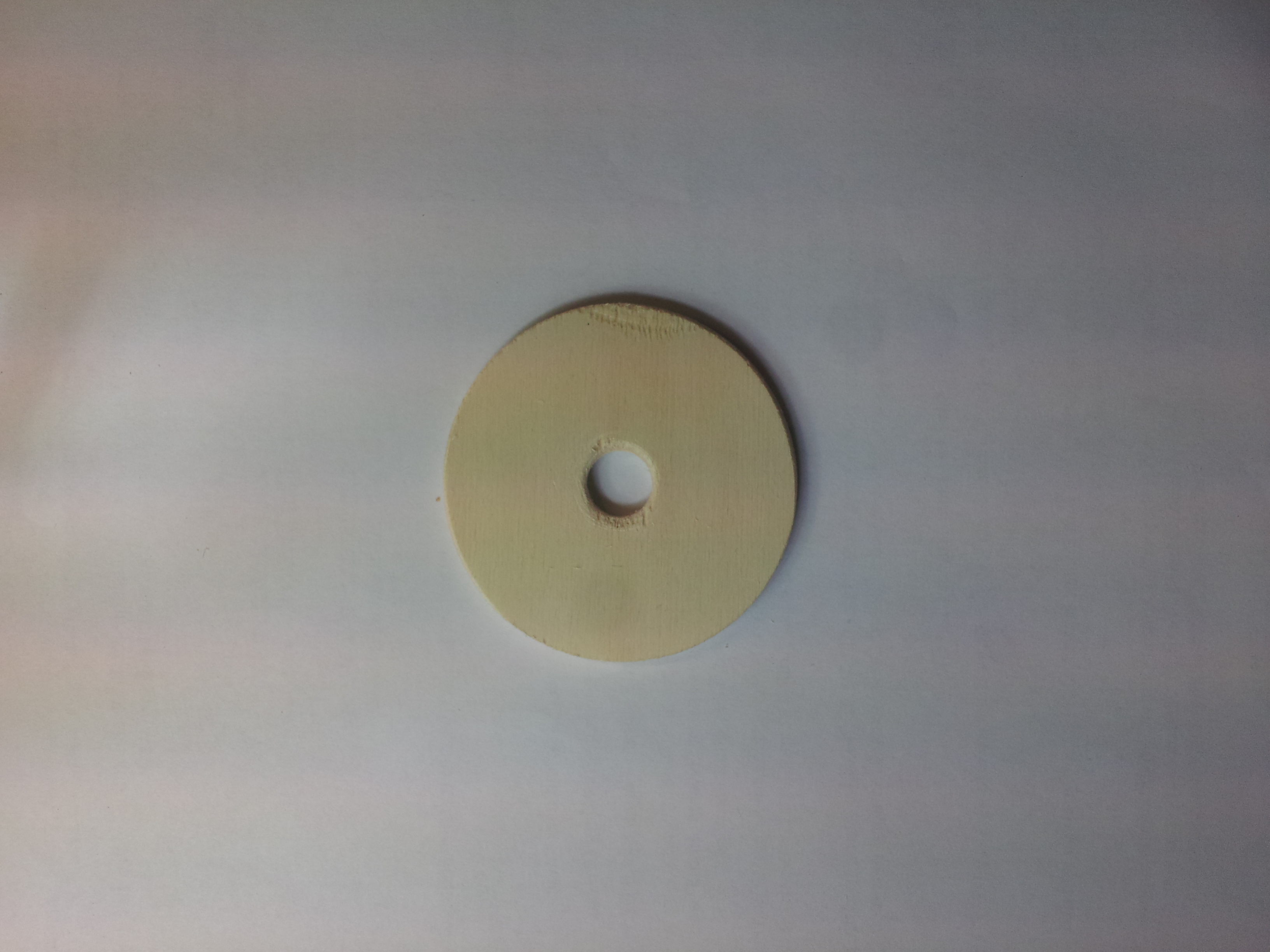
Next you have to drill the holes for the control threads. I used four holes because then we can fix to sides and control two sides for the movement. But if you want to build a tentacle with more movement control, you could use more holes ( you could also use only three holes, then you have to calculate more for the movement; same principle as with the quad-copters). Next you have to drill the holes for the controlling threads. For the big (68 mm) disks I align them on a circle with radius of 24 mm around the center. This is just 1 cm less then the radius of the disk. The diameter of the control holes amounts 5 mm.
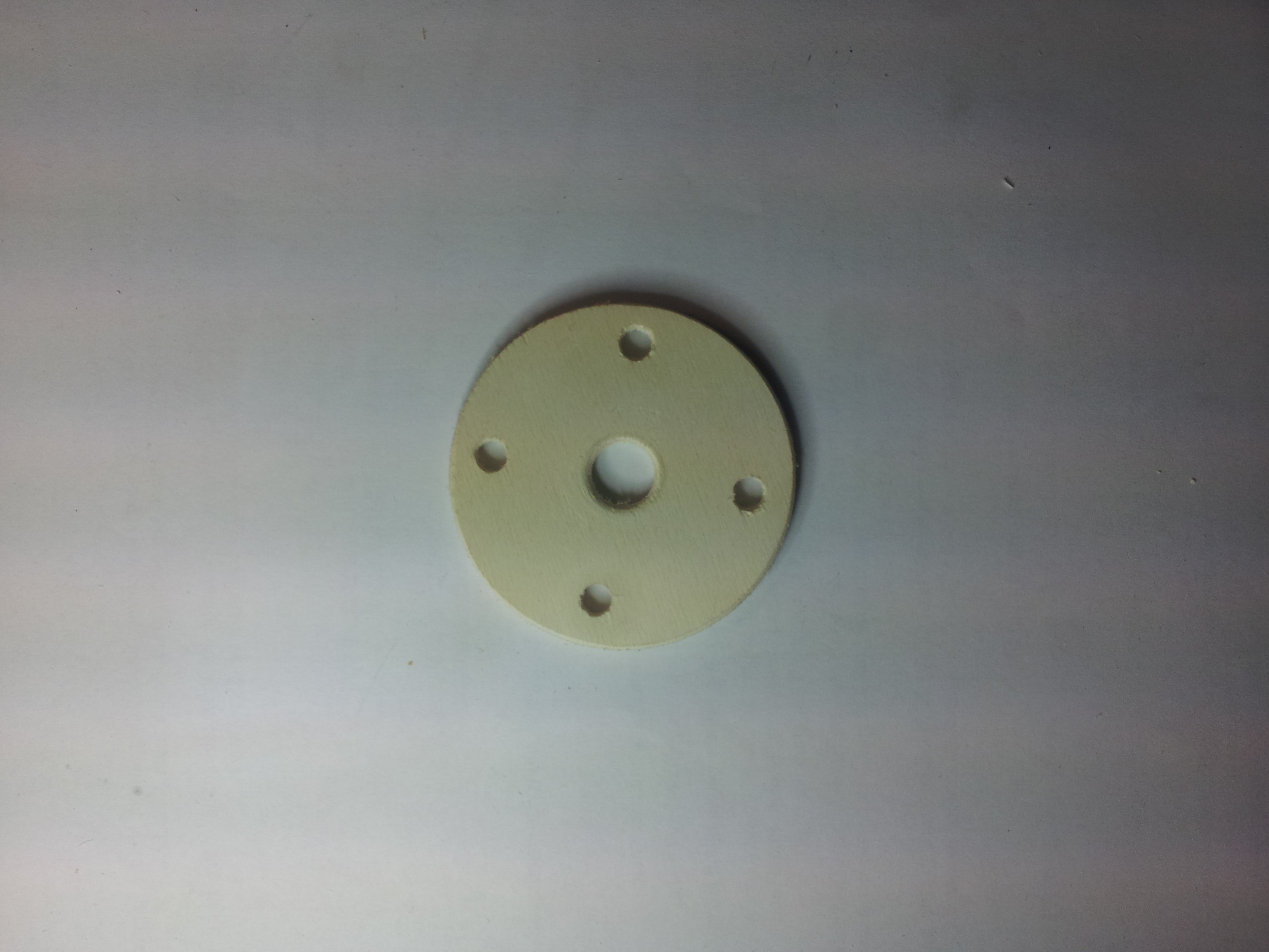
This is how the wooden disk should look after this step. Next you have to apply the cable gland screws and put them aside.
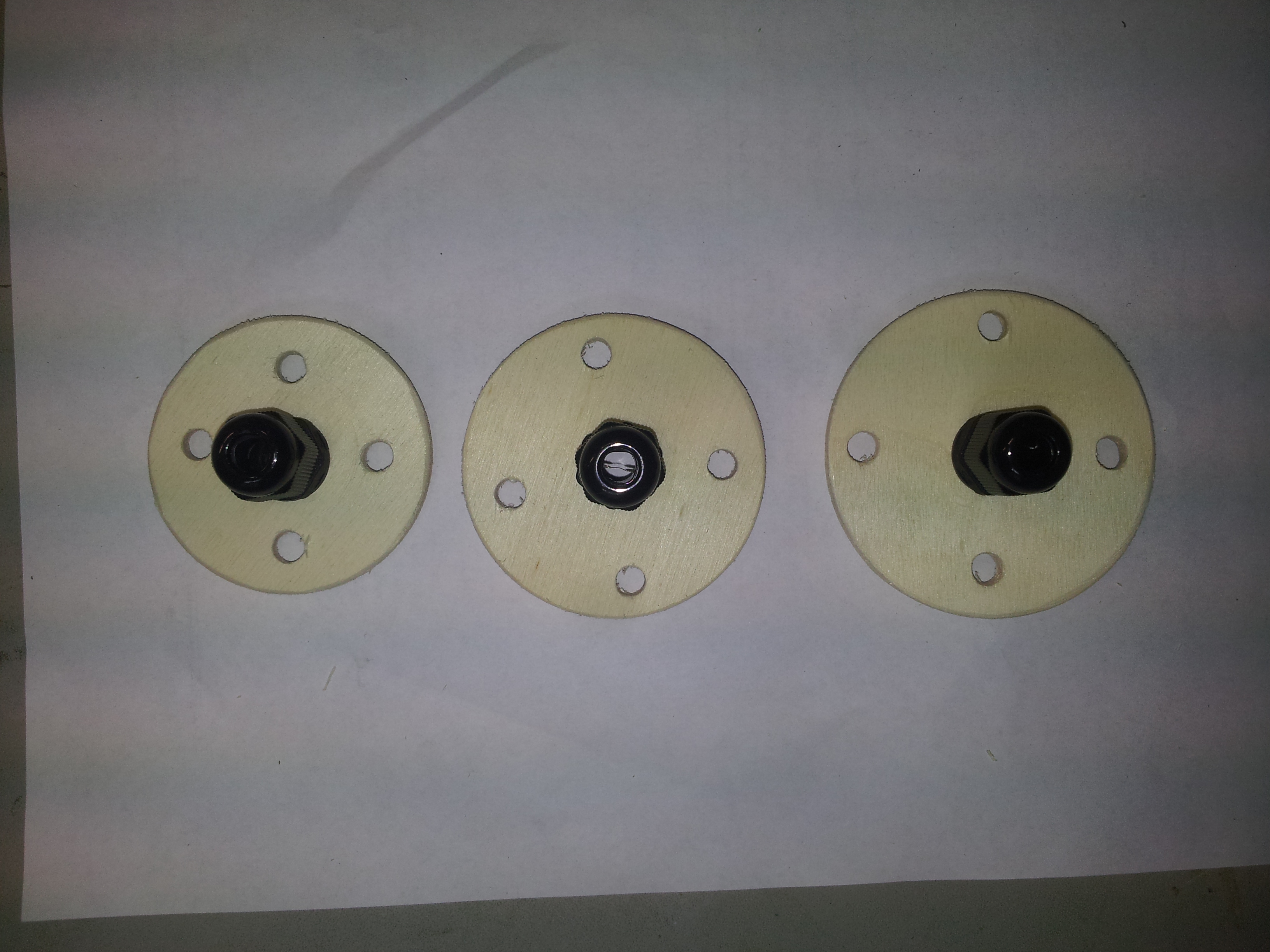
This was the fiddly work. The next steps will be more straight forward.
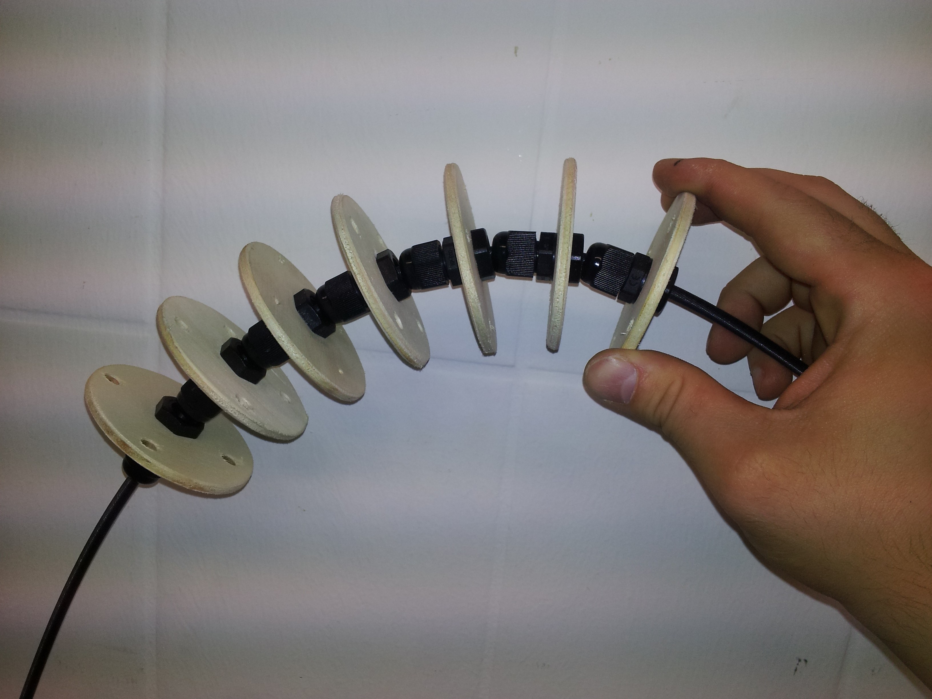
Step 2: Assembling the spine
Now you can take the disk with the screws and 1 m of your soul (here the flexible shaft) and put them together. Leave 12 cm from the top of the shaft and place the first disk there. The 12 cm are used to mount the tentacle later to the costumes. The first 6 disks have nearly no space in between to stiffen this part. Therefore it will stick out of the costume a little bit and not just hanging down. The next disks have a distance about 4.5 cm. The two last disks are the smaller one to indicate the tip of the tentacle.

Step 3: Attach the controlling threads
The last step is to attach the controlling threads. I used 1.6 m for the movable threads and 1.2 m for the fixed dimension. You should take care about the tip. To have a smooth movement the threads should placed carefully as you can see below.

This is how the tentacle mechanism is built. The controlling threads are then attached to a motor. The movement will be described in another post.
Material Experiments
First try of brain form. This is for the strip LED light to fix on it.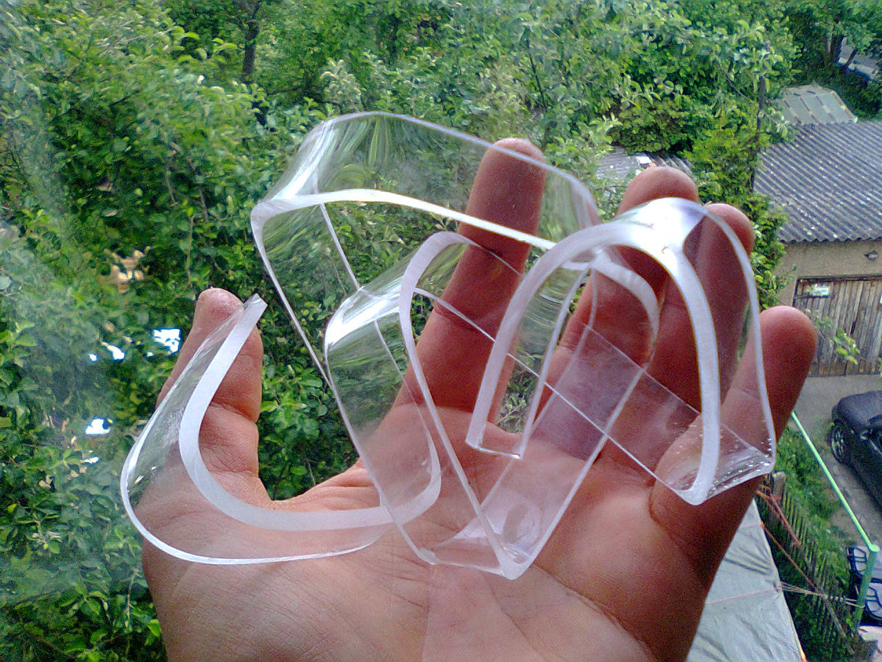
first test of the head

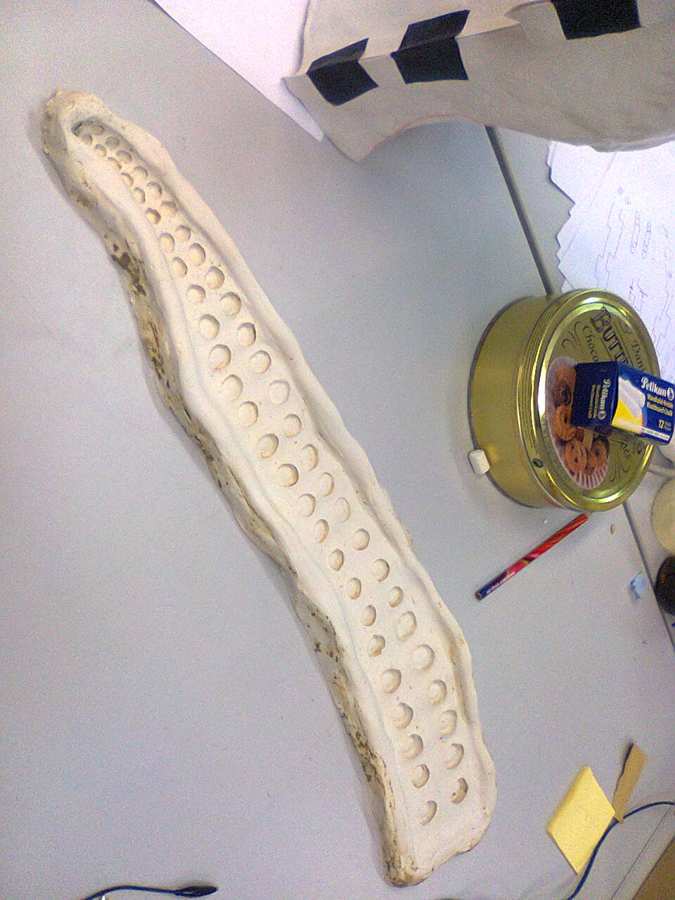
first silicon form of the back part legs