I decided to optimize a stopcock, because the load case is very interesting:
The forces and torsion have to be transferred from an outer circle to an axis in the middle.
There are two main aspects in the design:
1. A good possibility for grabbing the edge with your fingers or your hand, depending on the size.
2. The middle part where the force is transferred to the axis because the stopcock is a single element that is plugged to the axis.
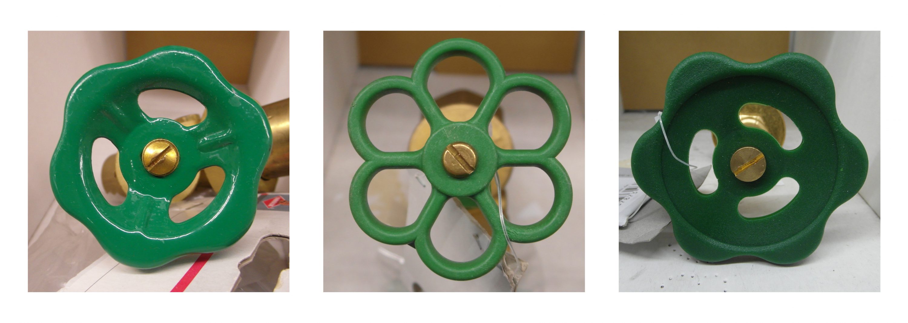
Today most of the commonly used stopcocks are produced form plastic as injection moulding, some are also made from sheet metal. The stopcock is attached to the axis with a square cross-section.
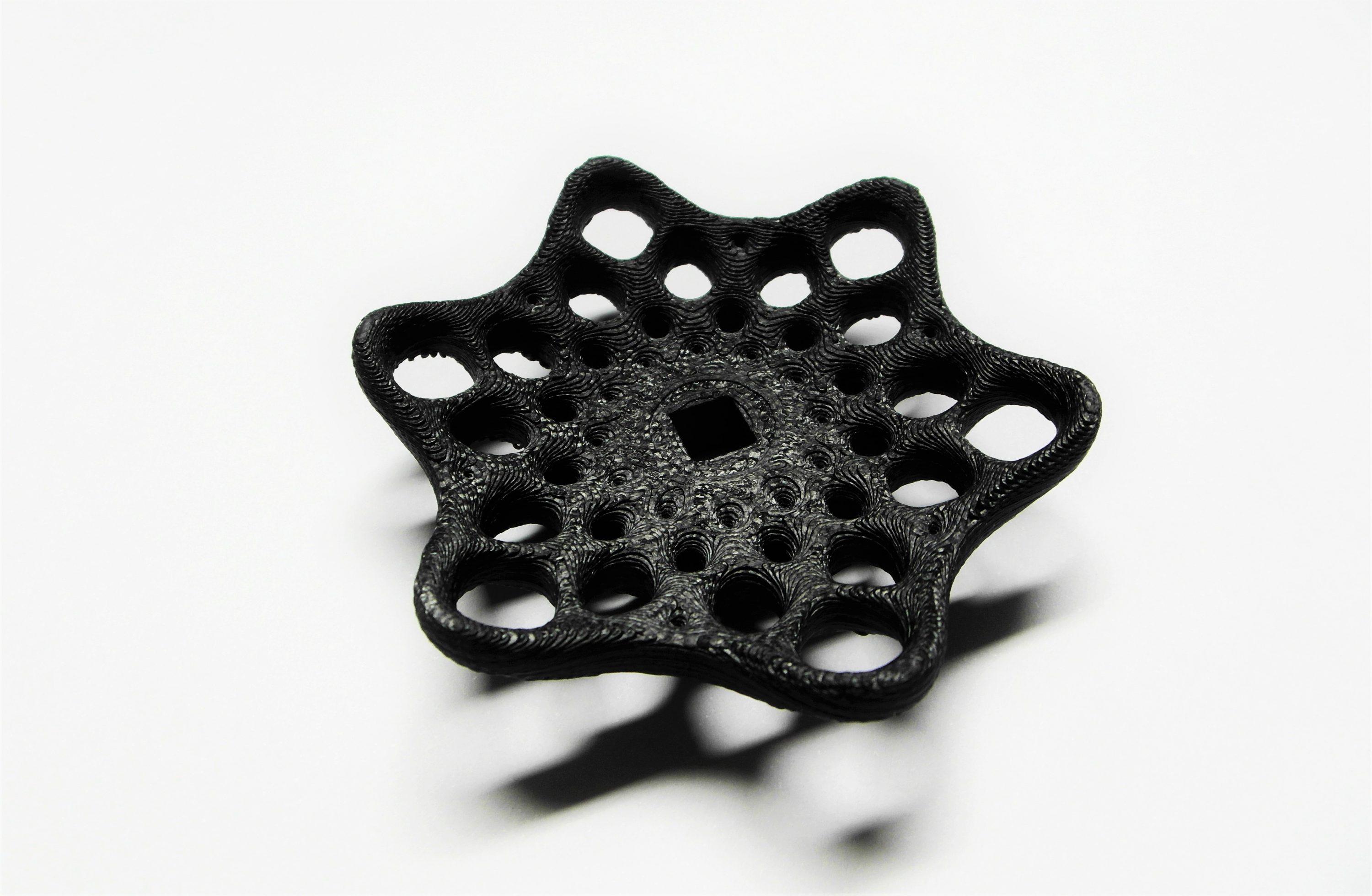
The 2D calculations resulted in different results depending on the number of corners. Some calculations were very rotationally symmetric, some had a more defined direction. For my design I choose a rotationally symmetrical shape because it resembled the turning of the stopcock.
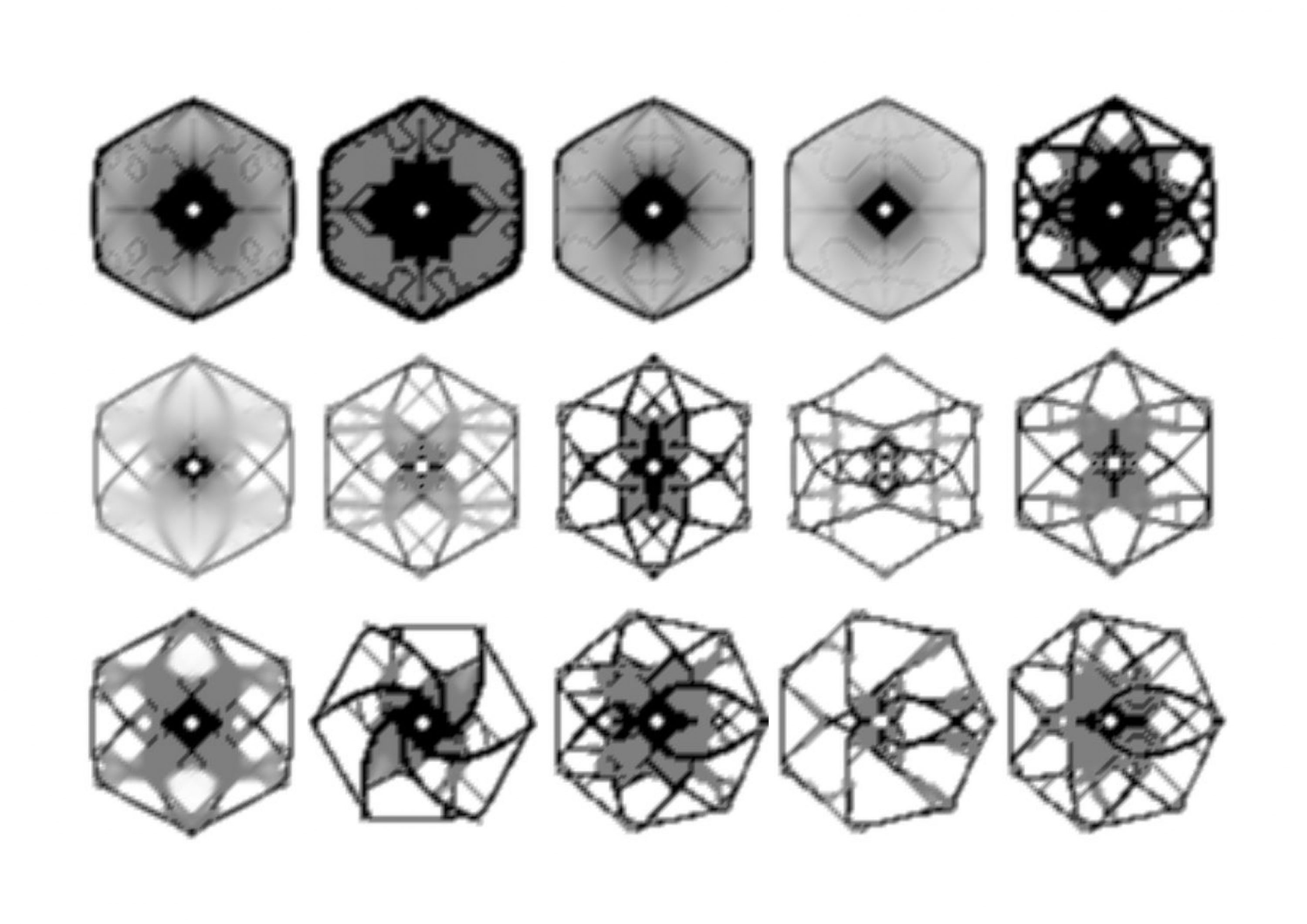
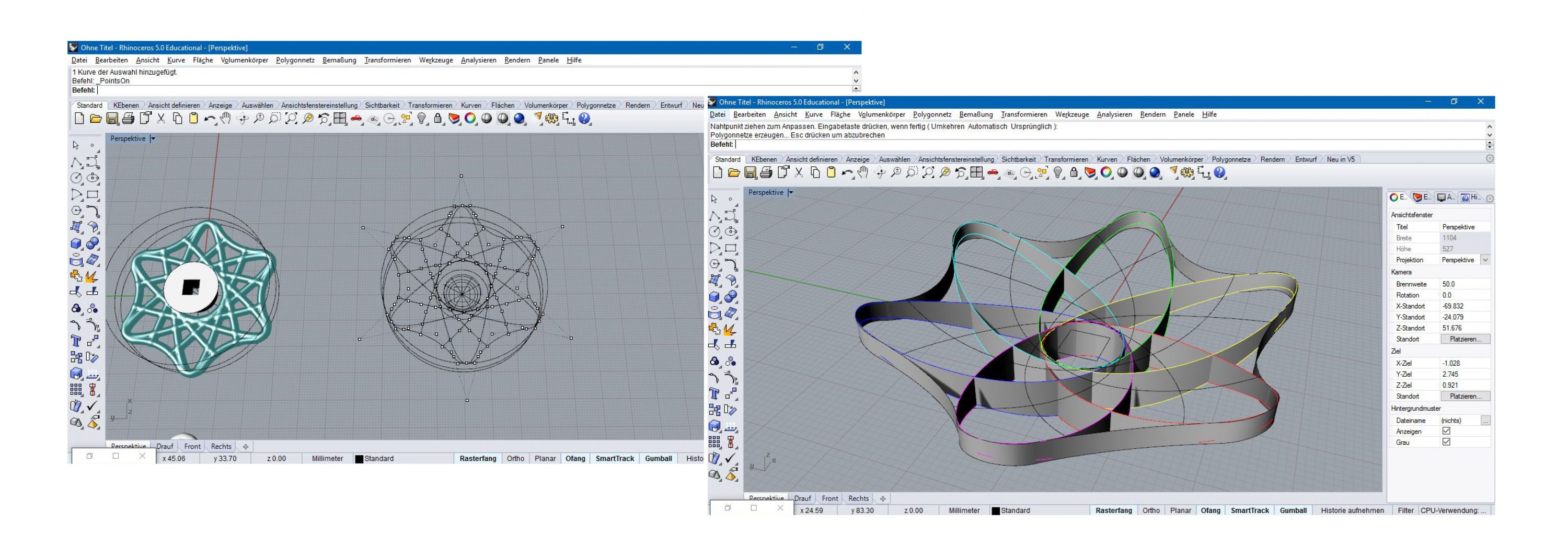
In the moment I am working on the construction of different forms and variations in CAD.
A version with six corners was 3D printed today and is very comfortable.
A critical aspect here is the combination of the new design with the square cross-section.