Note: You can download this documentation as PDF file.
Introduction
Goal of the workshop was to repurpose a possible cheap USB webcam into a microscope. Max Neupert, the organizer of this workshop, told us how to achieve this and instructed us throughout the winter term 2012/13.
The basic concept Max told us is pretty simple: just disassemble the camera, mount the lens upside down and shoot some great photos with the new microscope.
Disassembling the Camera
The "Hama PC-Webcam AC-150" served as a basis, which costs about € 5 when ordering via Amazon. It has a resolution of 640x480 pixels and six LEDs to lighten the scene. Beyond this, the camera supports UVC (USB Video Class), which is important for viewing live images directly on the screen.
As mentioned before, the first step was to disassemble the camera. After cracking the case, six LEDs had to be removed. In order to do so, we had to heat the solder at the back side of the PCB (printed circuit board). The last important step was to mount the lens with hot glue upside down onto the PCB. A photo showing this state of the microscope will follow soon.
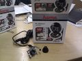
PCB without camera case
next to its original package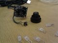
PCB with unsoldered
LEDs in front


The resulting microscope has a magnification area of 0.35mm x 0.46mm. This can be calculated by counting the visible pixels of a display with known ppi-specification. In my case the microscope shows 3x4 pixels with a length of 0.117mm per pixel (HTC HD2 has 217 ppi).
Building a Case


Since a microscope is designed to show very small objects, it is not appropriate to hold the camera in the hand because of uncontrollable hand movements. Therefore we needed to build a case that holds the microscope and gives the possibility to do little adjustments in height (that’s our zoom).
My approach basically consists of two sleds that lie on one another where the contact surface is a plane in the angle of 15 degrees to the table. Pushing the lower carriage to the left will force the upper carriage to move upwards. The first image on the right shows a technical side view drawing, the second one shows a rendered image.

After building a prototype out of Balsa wood, I was able to prove that the construction works fine. Nevertheless, some minor changes to the model have been done before printing the parts with a RapMan 3D printer. In the image below, that shows the two printed sleds carrying the microscope, one can notice that a M4 threaded rod was stuck through the lower sled and two counter nuts were fastened at each side of the sled, whereas the original plan was to have a screw head lying in a little pocket.

A M4 thread has a pitch of 0.7 mm, which means that one rotation about its own axis will move the lower sled 0.7 mm and therefore the upper sled about 0.2 mm. As a result, the microscope can be adjusted very fine in its height.
Note: As the 3D printer is broken at the moment, the case is built out of Balsa wood. An image of the actual model will be uploaded as soon as possible.
WebcamCapture Application

Because of the lack of simple applications which just show the current image of the webcam, I wrote a little program that does exactly this.
The application can be downloaded here, but note that the program only runs under Windows and .NET Framework 4 has to be installed.
Usage:
- Space bar - Save image to file
- R - Record video to AVI file
- N - Add suffix to filename (so you can identify your object later on)
- Escape - Exit application
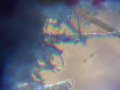
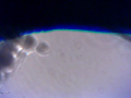
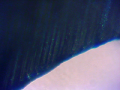
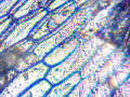
First images
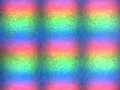
Here are my first images taken with the microscope. Unfortunately, on almost all images one can see a blot (probably hot glue). I will get another camera and try to do better work.
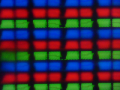
Display of HTC HD2
Glass of iPhone
Paper shred

Hair
Knife blade (1)
Knife blade (2)
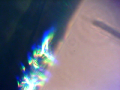
5 Euro note
Onion skin


A little video will be uploaded later.