Inspiration
- Brainy the Brain Badge
- Space Girl Soldering Kit
- I voted - Blinky Badge Soldering Kit
- #electionday2020
- The Plaque Doctor by Micheal Merrill
- COVID-19 Ultrasonic Distance Warning Tool
Working with KiCad and Inkscape
After my first attempts to create something nice looking in KiCad using Inkscape I was able to actually build a couple of little projects to get along with the program and to train using it.
Here you can see a circuit which includes a blinking LED. The first try was a round shaped PCB. Later I updated it, chose smaller components, put them on a rectangular plate and added some script. The function is still the same.


This is a little pendant in the shape of a star. I added a plated through-hole to turn it into a keychain.

To get in the Christmas mood I created two more batches. The first one is a gingerbread man which can be used as a pin (the dot on its back marks where the pin shall be added later) and the other one is a Christmas ball (also with a through-hole to hang it on the tree).


My Project
Project Concept
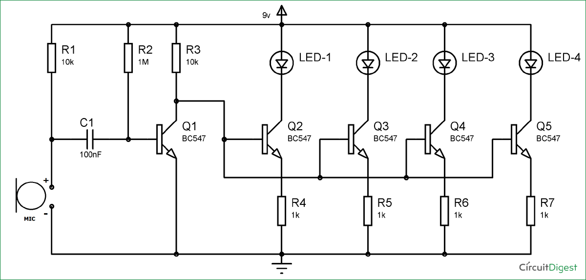
To figure out what I want to do as my final project, I surfed the internet to come to know what kind of circuits I can built. After searching for the possibility to make LEDs blink in different rhythms, I found a way to let an LED blink following the rhythm of music.
About the circuit:
- Components: resistors, capacitors, transistors, LEDs, switch, battery and microphone
- The length of the LED flash depends on the capacity of the capacitor (e.g. 2.2 μF ≈ 1 s). The higher the capacity, the longer the LED blinks.
- Tutorial and example circuit
- Depending on the amount of LEDs you want you can expand the circuit.
My idea:
Thinking about how I can include a circuit like that in a PCB with an artistic touch, I collected some ideas and sketches.
The rhythm following LEDs create a party atmosphere, so I'd like to build something that can be used in a party like situation as a mixture of decoration and play of light. To make it more useful I also want it to be ornamentally in every other circumstance, like a picture on the wall with an additional light effect. My thought was that it would be more comfortable if you have no need to put it down when you don’t use the effect. After experimenting with the different layers of the PCBs and finding out how to use them to make graphics, I wanted to create a black (solder mask) and white (silkscreen) picture with some highlights (copper mask – gold/silver). The size shall be not bigger than A4.
The LEDs will be used as a frame for the picture or elements in the graphic which shine naturally (e.g. stars). Also I thought about making two different circuits at once, so a couple of LEDs glow all the time while some others blink. Because the picture is kept simple I can imagine using LEDs in different colors to make a nice contrast.
Project Implementation
Finally I decided to draw an UFO in the universe. The blinking LEDs shall be components of the UFO itself and the shining LEDs the stars around it. I started working on a prototype and trying out different components and variable arrangements.


About the circuit
- The circuits consist of nine (UFO) and five (stars) LEDs (D1 to D14). They are connected so it is possible to only use one switch (SW1) to turn all the lights on.
- To extend the usability I used two batteries (BT1 and BT2).
- There has not been the right footprint in the library for the microphone I wanted to use. I worked with the footprint editor in KiCad to create a new one.


To check if the circuit works before ordering the PCBs, I built it on a simple circuit board. The circuit itself works but I recognized that its perception of the auditory signal is very low.
The make it more sensitive, I doubled a part in the beginning of the circuit - two resistors, the capacitor and one of the transistors (R17, R18, C2 and Q10). This change effects that the LEDs blink although the sound source is more quiet or more distant from the microphone.
SMD components (per PCB):
- 01x switch
- 01x microphone
- 02x battery (3V)
- 02x capacitor (47nF)
- 11x transistor
- 14x LED (white, red, green, blue, yellow, orange)
- 2x resistor (1MΩ)
- 3x resistor (10kΩ)
- 14x resistor (68Ω)
About the design
To connect the PCB and the components so that the design looks still nice I figured out some simple methods:
- I found the possibility to work with through-hole-components. That means the LED is soldered on the back of the PCB but through a hole it is visible on the front side. This avoids the PCB tracks on the front of the plate.
- The microphone has to be placed on the front of the plate because it needs to sense sound and music. To make it more inconspicuous I created a little planet looking like Saturn. The silkscreen is the ring around it and the microphone the planet itself.
- I had some problems with connecting the tracks. One of the connections was not possible, so I had to set two plated-through holes to create a „bridge“. It is set in one of the copper stars, so it was not necessary to make an extra track. It is not completely invisible but you can only see two little holes.
- Additionally I added a small rectangular copper area on the back side. To attach the PCB to the wall I am going to solder a piece of wire in shape of a semicircle to use it as a hanger assembly.


Outcome
This is what the PCB layout and the 3D model look like in KiCad:


And this is the PCB I received:


My final PCB is made of a a black solder mask and accented with silver copper and white silkscreen. It is 1.2mm thin and has a diameter of 15cm.
The copper mask is very damageable and a little bit scratched on one of the plates. All in all the PCB gives the impression of being stable and looks like I expected it.
Soldering
To solder the components on the PCB I used soldering paste. You just put a little amount on the footprint and put the component very carefully on top with the help of tweezers. Afterwards it is heated up until the paste melts and connects the component and the plate. Some elements became a bit crooked on my first attempt of soldering but it doesn’t qualifies the functionality. While working I noticed that some of the diodes I ordered are too big for the through-holes (less than one millimeter). So I had to drill the holes a little more but this it not visible in the final result. Also my battery holders are smaller than the footprint but luckily it was no problem to solder them anyway.


Because I had some more resistors than I needed I started experimenting with them. I used resistors with different values for the circuit of the white stars (between 0Ω and 1kΩ). As a result I changed the intensity of the single LEDs. So now I have got a variety of luminosity just like in the real universe - depending on how far the star/planet is away from you, the lighter or darker it shines.


As an attachment I took a short wire and cut off the synthetic material at the endings. I tied the endings and soldered them on the copper area I made for the hanger.


Aaand here we go: