No edit summary |
No edit summary |
||
| (18 intermediate revisions by 2 users not shown) | |||
| Line 1: | Line 1: | ||
==IDEA== | |||
My idea is to control a small set of | My idea is to control a small set of LED lights alongside with the music I program using MSP in order to create a visual sequence. I plan on building a small structure which is illuminated with a LED light strip smoothly alongside with the rhythm of the music, like you can see in the following videos: | ||
[https://www.youtube.com/watch?v=_QrF_CfAFEY Color LED light bulb ] In this reference, the developer used a microphone in order to alternate the change of colors according to the information received by the microphone. | [https://www.youtube.com/watch?v=_QrF_CfAFEY Color LED light bulb ] In this reference, the developer used a microphone in order to alternate the change of colors according to the information received by the microphone. | ||
| Line 11: | Line 9: | ||
This is a much more simpler example of installation with only three LED lights, in the original video, the lights dance to the music. [https://www.youtube.com/watch?v=Yd3hzYAJzOo Bottle LED light] | This is a much more simpler example of installation with only three LED lights, in the original video, the lights dance to the music. [https://www.youtube.com/watch?v=Yd3hzYAJzOo Bottle LED light] | ||
'''RESEARCH''' | |||
[[Background search]] | |||
==PROCEDURE== | |||
'''FIRST ATTEMPT''' | |||
In the first attempt, I tried using the 16 channel Relay Module and using the Christmas light tutorial. I was able to upload a code to it, but it wasn't being transmitted to the LED light installation. | |||
<gallery> | |||
File:Gracia1.jpg | |||
File:Gracia2.jpg | |||
File:Gracia3.jpg | |||
File:Gracia4.jpg | |||
</gallery> | |||
It was a little frustrating, as it was the winter break and couldn't really move forward with this technique. I kept looking online for an easier way for me to be able to communicate Max and Arduino with the LED lights. | |||
A little while later, I found a very helpful tutorial, which allowed me to communicate arduino with my set of LEDs. [https://learn.adafruit.com/rgb-led-strips/arduino-code]. I followed this tutorial and to my surprise, it really worked. | |||
<gallery> | |||
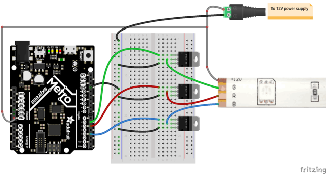
File:led-strips-ledstripfet.gif | This is the arduino connection I used as instructed by the tutotial | |||
File:Gracia6.jpg | And this is my connection: | |||
</gallery> | |||
And here you can find the video of when it first worked. | |||
{{#ev:youtube|HBzK3ENtR24|700x420}} | |||
'''CONNECTING THE CODE TO MAX''' | |||
''' | In this point, I talked to my teacher Miga, and he gave me a little clue to try to use the old patch I had used in a previous exercise and try to connect it to the new code I had in the arduino software. I tried several ways, until I realized that the easiest way was exactly modifying the code I had already programed a while before. | ||
So, here you have it: Max code, arduino code, and a video of the LED lights synchronized to any audio source the Computer's microphone detects. | |||
'''FINAL PROCESS''' | |||
Also seen in the website: https://learn.adafruit.com/rgb-led-strips/overview | |||
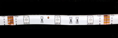
''There are two basic kinds of LED strips, the "analog" kind and "digital" kind. Analog-type strips have all the LEDs connected in parallel and so it acts like one huge tri-color LED; you can set the entire strip to any color you want, but you can't control the individual LED's colors. They are very very easy to use and fairly inexpensive. | |||
'' | |||
The LED lights used in this project are analog ones. | |||
https://i.postimg.cc/Qtn5J6cm/led-strips-analogstrip-t.jpg | |||
''Because there are three LEDs in series, you cannot drive these LEDs from a 5V supply. The LED strips say "+12V" on them to mark the anode and that's the maximum voltage we suggest. Each segment of 3 LEDs draws approximately 20 milliAmperes from a 12V supply, per string of LEDs. So for each segment, there is a maximum 20mA draw from the red LEDs, 20mA draw from the green and 20mA from the blue. If you have the LED strip on full white (all LEDs lit) that would be 60mA per segment.'' | |||
https://i.postimg.cc/pdcBXQqw/led-strips-wires-t.jpg | |||
I had to look for a 12V power supply that would be capable of powering up the whole system. I also has to solder cables from each RGB channel, and a 4th one for the power. Until it looked a like this: | |||
https://i.postimg.cc/zGVvYnHb/led-strips-heatshrunk-t.jpg | |||
Once the LED stripe was ready, I had to fix the arduino board and the breadboard in order to be able to control each LED channel individually. For this, I needed MOSFETS: | |||
''Because these LED strips are very simple, we can easily use them with any microcontroller. Since each 'LED' pin may end up requiring an Amp or more to sink to ground, power transistors are required! Don't try to connect the pins directly to your everyday microcontroller, they will burn out and/or not work. | |||
You can use any power NPN or N-Channel MOSFET, make sure the transistor is rated to be able to pass as much current as you need. For example, since we draw about 0.2Amps per channel per meter, if you have a 5 meter strip you will need to pass up to 1 Ampere per transistor. Get the beefy "TO-220" packages, not the dinky little guys. Make sure they look like this:'' | |||
https://i.postimg.cc/ | https://i.postimg.cc/TPNZMDmw/led-strips-7805-t.jpg | ||
And the connection in the breadboard goes like this: | |||
https://i.postimg.cc/qvbmzd7D/led-strips-ledstripfet.gif | |||
As you can see. Each cable we soldered to the LED stripe, was placed in the middle leg of each MOSFET. Each right led was connected to another cable that went to the channel 5, which is the main controller in the arduino code. And each left leg, was connected by bridge to the ground in the arduino board. The extra cable for the LED stripe power supply was not connected as shown in the picture, it was connected directly to the 12V power supply. | |||
Arduino code: [[:File:sketch_mar12a.ino]] | Arduino code: [[:File:sketch_mar12a.ino]] | ||
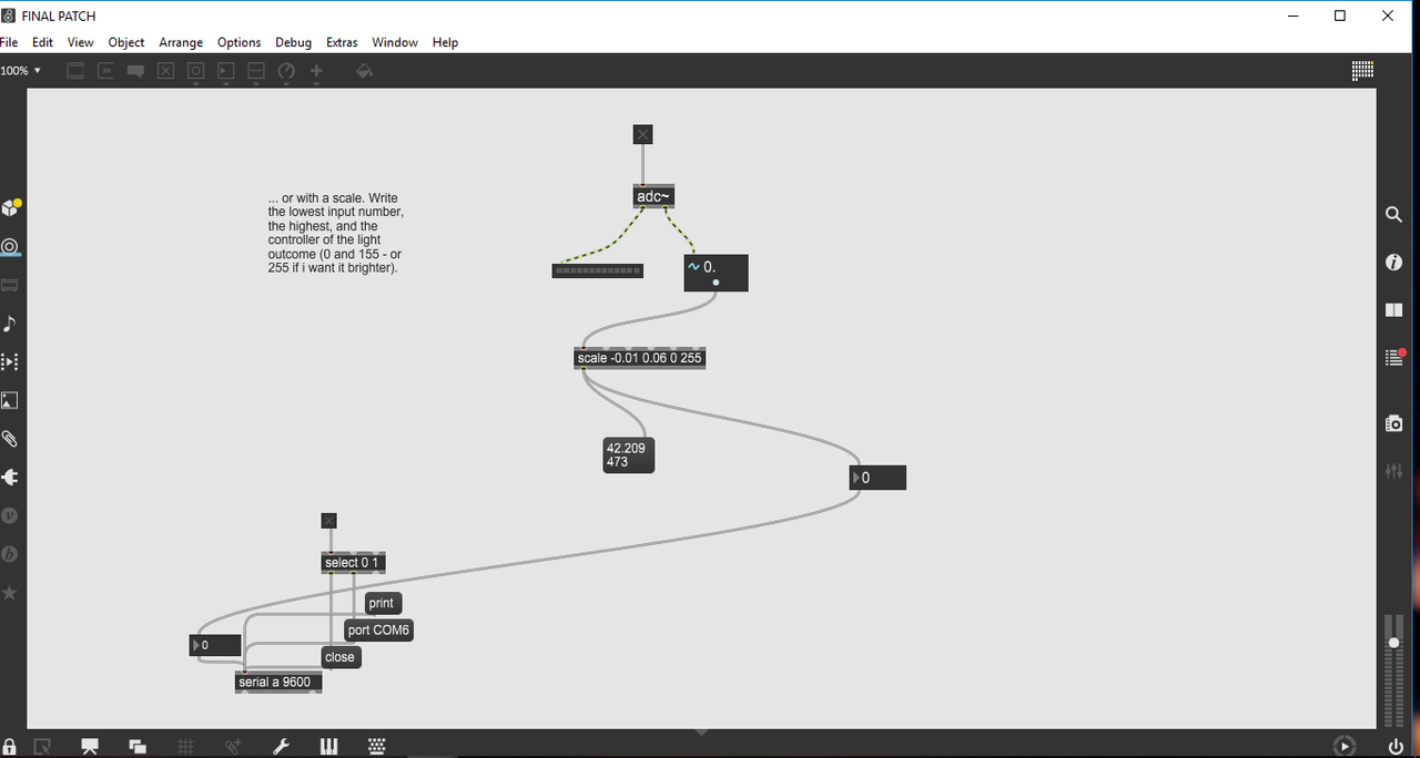
MAx code: [[:File:FINAL PATCH.maxpat]] | MAx code: [[:File:FINAL PATCH.maxpat]] | ||
Final Connection: | https://i.postimg.cc/4dVyYsXz/Untitled.png | ||
https://i.postimg.cc/ | |||
'''Final Connection:''' | |||
https://i.postimg.cc/4NBCbqdV/led-strips-m0-analog-rgb-bb.png | |||
<gallery> | |||
File:Gracia_a.jpg | |||
File:Gracia_b.jpg | |||
File:Gracia_c.jpg | |||
File:Gracia_d.jpg | |||
</gallery> | |||
{{#ev:vimeo|328945477|640 x 480}} | |||
{{#ev:vimeo|328945435|640 x 480}} | |||
{{#ev:vimeo|328945387|640 x 480}} | |||
{{#ev:vimeo|328945366|640 x 480}} | |||
==Homeworks== | |||
[[/Homeworks]] | |||
Latest revision as of 15:32, 7 April 2019
IDEA
My idea is to control a small set of LED lights alongside with the music I program using MSP in order to create a visual sequence. I plan on building a small structure which is illuminated with a LED light strip smoothly alongside with the rhythm of the music, like you can see in the following videos:
Color LED light bulb In this reference, the developer used a microphone in order to alternate the change of colors according to the information received by the microphone.
This is a much more simpler example of installation with only three LED lights, in the original video, the lights dance to the music. Bottle LED light
RESEARCH
PROCEDURE
FIRST ATTEMPT In the first attempt, I tried using the 16 channel Relay Module and using the Christmas light tutorial. I was able to upload a code to it, but it wasn't being transmitted to the LED light installation.


It was a little frustrating, as it was the winter break and couldn't really move forward with this technique. I kept looking online for an easier way for me to be able to communicate Max and Arduino with the LED lights.
A little while later, I found a very helpful tutorial, which allowed me to communicate arduino with my set of LEDs. [1]. I followed this tutorial and to my surprise, it really worked.

This is the arduino connection I used as instructed by the tutotial
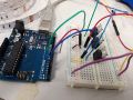
And this is my connection:


And here you can find the video of when it first worked.
CONNECTING THE CODE TO MAX
In this point, I talked to my teacher Miga, and he gave me a little clue to try to use the old patch I had used in a previous exercise and try to connect it to the new code I had in the arduino software. I tried several ways, until I realized that the easiest way was exactly modifying the code I had already programed a while before.
So, here you have it: Max code, arduino code, and a video of the LED lights synchronized to any audio source the Computer's microphone detects.
FINAL PROCESS Also seen in the website: https://learn.adafruit.com/rgb-led-strips/overview
There are two basic kinds of LED strips, the "analog" kind and "digital" kind. Analog-type strips have all the LEDs connected in parallel and so it acts like one huge tri-color LED; you can set the entire strip to any color you want, but you can't control the individual LED's colors. They are very very easy to use and fairly inexpensive. The LED lights used in this project are analog ones.
Because there are three LEDs in series, you cannot drive these LEDs from a 5V supply. The LED strips say "+12V" on them to mark the anode and that's the maximum voltage we suggest. Each segment of 3 LEDs draws approximately 20 milliAmperes from a 12V supply, per string of LEDs. So for each segment, there is a maximum 20mA draw from the red LEDs, 20mA draw from the green and 20mA from the blue. If you have the LED strip on full white (all LEDs lit) that would be 60mA per segment.
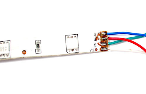
I had to look for a 12V power supply that would be capable of powering up the whole system. I also has to solder cables from each RGB channel, and a 4th one for the power. Until it looked a like this:

Once the LED stripe was ready, I had to fix the arduino board and the breadboard in order to be able to control each LED channel individually. For this, I needed MOSFETS:
Because these LED strips are very simple, we can easily use them with any microcontroller. Since each 'LED' pin may end up requiring an Amp or more to sink to ground, power transistors are required! Don't try to connect the pins directly to your everyday microcontroller, they will burn out and/or not work.
You can use any power NPN or N-Channel MOSFET, make sure the transistor is rated to be able to pass as much current as you need. For example, since we draw about 0.2Amps per channel per meter, if you have a 5 meter strip you will need to pass up to 1 Ampere per transistor. Get the beefy "TO-220" packages, not the dinky little guys. Make sure they look like this:

And the connection in the breadboard goes like this:
As you can see. Each cable we soldered to the LED stripe, was placed in the middle leg of each MOSFET. Each right led was connected to another cable that went to the channel 5, which is the main controller in the arduino code. And each left leg, was connected by bridge to the ground in the arduino board. The extra cable for the LED stripe power supply was not connected as shown in the picture, it was connected directly to the 12V power supply.
Arduino code: File:sketch_mar12a.ino
MAx code: File:FINAL PATCH.maxpat
Final Connection: