(Updated material and sketches from 21.11.) |
|||
| Line 574: | Line 574: | ||
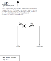
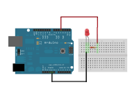
=== I Blinking LED === | === I Blinking LED === | ||
[[File:LED_schematics.png|200px|thumb]] | |||
[[File:I_blinkingLED_fritzing_bb.png|200px|thumb]] | |||
<source lang="java"> | <source lang="java"> | ||
/* BLINKING LED | /* BLINKING LED | ||
| Line 609: | Line 610: | ||
delay(1000); | delay(1000); | ||
} | |||
</source> | |||
<br /><br /> | |||
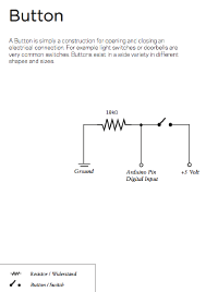
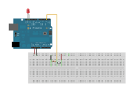
=== II Pushbutton === | |||
[[File:Pushbutton_schematic.png|200px|thumb]] | |||
[[File:II_pushbutton_arduino.png|200px|thumb]] | |||
<source lang="java"> | |||
/* PUSHBUTTON | |||
* | |||
* Here we connect a pushbutton to the digital pin 2. | |||
* When the button is pressed, the LED on port 13 | |||
* (the internal one), starts blinking. | |||
* | |||
*/ | |||
int myLedPin = 13; // LED pin | |||
int myButtonPin = 2; // input pin (for the pushbutton) | |||
int myButtonState = 0; // variable for storing the inputpin status | |||
void setup() { | |||
// declare the LED pin as output | |||
pinMode(myLedPin, OUTPUT); | |||
// declare the button pin as input | |||
pinMode(myButtonPin, INPUT); | |||
} | |||
void loop(){ | |||
// read the current state of the button pin | |||
// (either HIGH or LOW) and store it in the | |||
// variable myButtonState: | |||
myButtonState = digitalRead(myButtonPin); | |||
// whenever the button is pressed: | |||
// start the LED blinking | |||
if (myButtonState == HIGH) { | |||
digitalWrite(myLedPin, HIGH); | |||
delay(300); | |||
digitalWrite(myLedPin, LOW); | |||
delay(300); | |||
} | |||
// when the button is not pressed: | |||
else{ | |||
// turn off the LED | |||
digitalWrite(myLedPin, LOW); | |||
} | |||
} | } | ||
</source> | </source> | ||
Revision as of 11:14, 22 November 2011
This site belongs to the Physical Computing 2011 class.
24.10.2011 Processing sketches
I Simple shapes
/* SIMPLE SHAPES
 *
 * Get familiar with the coordinate system and the way
 * shapes are beeing drawn onto the screen.
 *
 * Frederic Gmeiner 2011
 */

// define the width and height of the display window:
// 400 x 400 px
size(400,400);

// draw the following shapes without outlines:
noStroke();
//set the fill color of the following shapes to pure red:
fill(255,0,0);
// draw a rectangle:
rect(230,230,50,100);
// set the fill color to pure green and draw a rectangle:
fill(0,255,0);
rect(200,200,50,100);
// set the outline color to pure blue:
stroke(0,0,255);
// draw the following shapes without any fill color:
noFill();
// draw a ellipse:
ellipse(100,100,20,20);
II Relations
/* RELATIONS
 *
 * Instead of using fixed values, we use variables
 * to formulate relations. In this example a structure
 * based on two vertical parallel lines with a circle
 * in between is formulated.
 *
 * Frederic Gmeiner 2011
 */

// variable to store the radius of the circle:
int rad = 40;
// variables to store the x and y position of the structure:
int startPointX = 100;
int startPointY =100;

size(400,400);

// left line starts at the defined values and has a length of 80px:
line(startPointX, startPointY, startPointX, startPointY+80);

// the ellipse in between the two lines has a radius of "rad",
// so the width and hight is "2*rad". Since ellipses have their
// origin in the middle in processing, we need to add the radius
// to our "startPointX" value to have it centered in between the lines:
ellipse(startPointX+rad, startPointY+40, 2*rad, 2*rad);

// the right line is set in relation to the width of the circle:
line(startPointX+(2*rad), startPointY, startPointX+(2*rad), startPointY+80);
III Functions
/* FUNCTIONS
 *
 * Here we define a custom function ("crossFunction()") which draws a
 * cross onto the screen.
 * It takes the parameters: X value, Y value and the size.
 * Also the continuous mode is introduced, which
 * uses the processing functions setup() and draw().
 * Via the pre-defined variables "mouseX" and "mouseY" we
 * can access the current mouse position.
 *
 * Frederic Gmeiner 2011
 */

// the setup() function is called everytime the program
// starts once.
void setup(){
  size(400,400);
}

// the draw() function is the main loop function of your program:
// after every operation in the draw function has been
// called, the draw function is called again. this
// goes on until the program quits.
void draw(){
  background(255);
  crossFunction(mouseX,mouseY,10);
}

// this is the definition of the custom function "crossFunction()":
void crossFunction(int crossX, int crossY, int crossSize){
  line(crossX-crossSize/2, crossY-crossSize/2, crossX+crossSize/2, crossY+crossSize/2);
  line(crossX+crossSize/2, crossY-crossSize/2, crossX-crossSize/2, crossY+crossSize/2);
}
IV Movement & conditions
/* MOVEMENT & CONDITIONS
 *
 * By changing a variable during the runtime,
 * we can alter the condition of the program.
 * Here we increment an integer variable
 * each time draw() is called. This variable is
 * used for the x-position of a line, thus
 * creating the illusion of a continuous movement
 * from left to right.
 * Via the "if" and "else" branches we can react
 * to different states of the program and alter it
 * accordingly.
 *
 * Frederic Gmeiner 2011
 */

// variable to store the x-position of the line:
int lineX = 0;

void setup(){
  size(500,300);
}

void draw(){
  // clear the background
  background(255);

  // if the x position of the line is larger than the middle of the screen:
  if(lineX > width/2){
     // change the stroke colour to pure red:
    stroke(255,0,0);
  // if the x position of the line is smaller than the middle of the screen:
  }else{
    // set the stroke coulour to black:
    stroke(0,0,0);
  }

  // draw a vertical line from the top (0) to the bottom ("height") at
  // the current x-position:
  line(lineX,0,lineX,height);

  // increment the lineX variable by 1
  // (you could also simply write "lineX++")
  lineX = lineX+1;

  // use the "println()" function to show the value of variables
  // in the console. this is helpful for debugging.
  println(lineX);
}
Exercise I: Bouncing Line
This is one possible solution to achieve that the line from the example above changes it direction when it reaches the left and right boundaries of the sketch window.
/* BOUNCING LINE
 *
 * This is a modification of the previous sketch
 * so that the line will bounce off the left and
 * right borders of the window. Notice the introduction
 * of the variable "speed" to control the speed and
 * direction of the moving line.
 *
 * Frederic Gmeiner 2011
 */

// variable to hold the currect x position of the line
int lineX = 0;
// variable that controls the speed and direction
int speed =1;

void setup(){
  size(500,300);
}

void draw(){
  background(204);

   // if the x position of the line exceeds the right border of the window:
   // change the direction by setting the speed to a negative value
  if(lineX > width){
    speed = -1;
  }
  // accordingly set the speed to a positive value as soon as the line touches
  // the left border.
  if(lineX < 0 ){
    speed = 1;
  }

  // here the new x position is calculated by adding the speed onto the
  // current x position. if speed is -1, lineX decreases. if speed is 1, lineX
  // increases.
  lineX = lineX + speed;

  // draw the line based on the calculated x position:
  line(lineX,0,lineX,height);
}
Exercise II: A frightened rectangle
Write a sketch that contains one rectangle with a size of 20x20px.
As soon as the mouse pointer is over the rectangle, the rectangle
starts to shiver.
Some useful hints:
07.11.2011 Processing sketches
Exercise I: Bouncing Line (Advanced)
/* BOUNCING LINE ADVANCED
 *
 * Notice the introduction of the variables
 * "speed" and "direction to control the speed
 * and direction of the moving line inependently.
 *
 * Frederic Gmeiner 2011
 */

// variable to hold the currect x position of the line
float lineX = 0;
// variable that controls the speed
float speed = 2.3f;
// variable that controls the direction
// (either 1 or -1)
int direction = 1;


void setup(){
  size(300,300);
}

void draw(){

  background(204);

   // if the x position of the line exceeds the right border of the window
   // OR (||) the x position of the line exceeds the left border
   // of the window:
  if(lineX > width || lineX < 0){
    direction = direction * -1; // change the direction
  }

  // here the new x-position is calculated by adding the speed and direction onto the
  // current x-position. if direction is -1, lineX decreases. if direction is 1, lineX
  // increases:
  lineX = lineX + (speed * direction);

  // draw the line based on the calculated x-position:
  line(lineX,0,lineX,height);
}
Exercise II: Solution
/* A FRIGHTENED SQUARE
 *
 * A little sketch to illustrate the random() function
 * and a more complex boolean equation to check whether
 * the mouse pointer is inside a rectangular shape.
 *
 * Frederic Gmeiner 2011
 */

// the x an y positions of the square:
float xPos = 200f;
float yPos = 200f;
// the width and height of the square:
int s = 20;

void setup(){
   size(400,400);
}

void draw(){
  background(204);

  // Here we check if the position of the mouse is somewhere inside of the
  // square. To know this, all these four contitions must be true ( && ):
  if( mouseX > xPos && mouseX < xPos + s && mouseY > yPos && mouseY < yPos + s){
      xPos += random(-2,3); // add a random value between -2 and 3 to the xPos
      yPos += random(-2,3);
      fill(40);
  }else{
    fill(255);
  }

  // finally draw the square:
  rect(xPos, yPos, s, s);

}
V for() loops
/* DYNAMIC DISTRIBUTION
 *
 * This sketch demonstrates the usage of
 * a for-loop for calculating and drawing
 * a certain number of ellipses according
 * to the changing mouseX position.
 *
 * Frederic Gmeiner 2011
 */


// the number of circles:
int numCircles = 15;

void setup(){
  size(500,200);
  stroke(255);
  fill(150);
  smooth();
}

void draw(){
  background(255);

  // calculate the distance between the circles
  // so that in total it results in the mouseX position:
  float distance = mouseX / (numCircles-1);

  // for every circle (numCircles) calculate the xPos
  // and draw it onto the screen:
  for(int i=0; i < numCircles; i++){
    float xPos = i*distance;
    ellipse(xPos,100,10,10);
  }
}
VI The array: a collection of variables
/* Random points in an array
 *
 * This demonstrates how to store values in
 * an array. This is useful when working with
 * many things which share the same parameters.
 * Here we use two arrays to store the coordinates
 * of circles.
 *
 * Frederic Gmeiner 2011
 */

// total number of circles:
int numCircles = 40;

// the radius of the circles
float rad = 20f;

// initializing two arrays for storing the x and y positions
// of the circles:
float[] xPositions = new float[numCircles];
float[] yPositions = new float[numCircles];


void setup(){

  size(500,500);
  smooth();
  noStroke();
  fill(150);

  // iterating over the arrays to set each position with
  // a random value based on the window size:
  for(int i=0; i< numCircles; i++){
    xPositions[i] = random(0,width);
    yPositions[i] = random(0,height);
  }
}


void draw(){

  background(204);

  // again iterating over the arrays. but this time we only
  // get the x and y coordinates to draw the circles:
  for(int i=0; i< numCircles; i++){
    ellipse(xPositions[i], yPositions[i], rad, rad);
  }

}
Exercise III
Modify the example VI so that the size of the circles changes over time using the sine function sin().
Helpful links:
sin() Example
General introduction (Try out the sketch by copy-pasting it into your processing editor)
14.11.2011 Processing sketches
EXERCISE III: SOLUTION
/* PULSING CIRCLES
 *
 * Mofification of the example above so that
 * the circles will shrink and grow by using
 * a sinewave.
 *
 * Frederic Gmeiner 2011
 */

int numCircles = 40;
float rad = 20f;

// initial angle of 0. this will increase during the
// runtime of the programm and will be used to calculate
// the sine based on this value in order so modify the size of
// circles.
float angle = 0.0f;
// how fast the angle will increase is defined by the speed variable:
float speed = 0.01;

float[] xPositions = new float[numCircles];
float[] yPositions = new float[numCircles];


void setup(){
  size(500,500);
  smooth();
  noStroke();
  fill(150);

  for(int i=0; i< numCircles; i++){
    xPositions[i] = random(0,width);
    yPositions[i] = random(0,height);
  }
}


void draw(){

  background(204);
  // add the speed value to the angle:
  angle += speed;

  // calculate the diamater by calculating the sine value of the
  // angle and scaling it up by the value of 30. This is necessary since
  // the sin() funtion returns only values between -1 and 1.
  float diameter = sin(angle)*30;

  for(int i=0; i< numCircles; i++){
    // draw the circles:
    ellipse(xPositions[i], yPositions[i], diameter, diameter);
  }
}
VII.a Another sine and cosine example
/* ELLIPTICAL MOTION
 *
 * A little demonstration of the sine and
 * cosine relation.
 *
 * Frederic Gmeiner 2011
 */

float speed = 0.1f;  // frequency
float angle = 0.0f; // you might also call it theta


void draw(){

  background(200);
  angle += speed;

  point(50,50);
  point(50+ (cos(angle)/2*50), 50+ (sin(angle)*50));

}
VII.b Relation of degree, PI and sine
int degr= 0;

println("0° Degrees:");
println("PI:" + radians(degr) / PI);
println("sine:" + round(sin(radians(degr))) + "\n");

degr= 90;
println("90° Degrees:");
println("PI:" + radians(degr) / PI);
println("sine:" + round(sin(radians(degr))) + "\n");

degr= 180;
println("180° Degrees:");
println("PI:" + radians(degr) / PI);
println("sine:" + round(sin(radians(degr))) + "\n");

degr= 270;
println("270° Degrees:");
println("PI:" + radians(degr) / PI);
println("sine:" + round(sin(radians(degr))) + "\n");

degr= 360;
println("360° Degrees:");
println("PI:" + radians(degr) / PI);
println("sine:" + round(sin(radians(degr))) + "\n");
VIII Reading data from a text file
Imports a data table from a textfile
with tab seperated values (tsv).
These
formats are very common when exporting
spreadsheets from Excel or similar software.
Make sure that the file "measurements.tsv"
exists in the data folder of this sketch.
Download: Media:PhysicalComp11 reading tsv.zip
21.11.2011 Arduino workshop sketches
I Blinking LED
/* BLINKING LED
 *
 * Demonstrates how to make a LED connected to digital pin 4
 * blink in an interval of 1 second.
 *
 * You could also use the internal LED on pin 13. This
 * LED is mounted onto the board with a resistor in between,
 * so whenn connecting a LED to pin 13 we don't need an extra
 * resistor.
 *
 */


// specifiy the pin for our LED
int ledPin = 4;

void setup(){
  // configure the pin of the LED as an output
  pinMode(ledPin, OUTPUT);
}


void loop(){

  // set the LED pin to HIGH (+5 Volts)
  digitalWrite(ledPin, HIGH);
  // wait for 1000 milliseconds = 1 second
  delay(1000);
  // set the LED pin to LOW (0 Volts)
  digitalWrite(ledPin, LOW);
  // again wait 1 second
  delay(1000);

}
II Pushbutton
/* PUSHBUTTON
 *
 * Here we connect a pushbutton to the digital pin 2.
 * When the button is pressed, the LED on port 13
 * (the internal one), starts blinking.
 *
 */

int myLedPin = 13;      // LED pin
int myButtonPin = 2;    // input pin (for the pushbutton)
int myButtonState = 0;  // variable for storing the inputpin status


void setup() {
  // declare the LED pin as output
  pinMode(myLedPin, OUTPUT);
  // declare the button pin as input
  pinMode(myButtonPin, INPUT);

}

void loop(){
   // read the current state of the button pin
   // (either HIGH or LOW) and store it in the
   // variable myButtonState:
  myButtonState = digitalRead(myButtonPin);

  // whenever the button is pressed:
  // start the LED blinking
  if (myButtonState == HIGH) {
      digitalWrite(myLedPin, HIGH);
      delay(300);
      digitalWrite(myLedPin, LOW);
      delay(300);
  }
  // when the button is not pressed:
  else{
    // turn off the LED
    digitalWrite(myLedPin, LOW);
  }
}


