Compositing
edit ~ 0 kommentare/fragen ~ 16. Dez 2015 20:46
;)
;)
;)
;)
;)
Hallo Workshopteilnehmer,
hier kommen die Materialien zu unserem Workshop zum download. Mit freundlichen Grüßen
Prof. Andreas Kästner
Beispiele für die Summaery-Präsentation
edit ~ 0 kommentare/fragen ~ 12. Jun 2015 11:37
;)
Dear seminar participants,
here you will find a reference file for your gif animated perspective construction result. For all has to fit in a 800 * 600 pixel screen and should have the same graphics appearance I send you as sample an ArchiCAD file in english and german on which base you should develop your construction. Fill in the construction title and your Names at the correct fields. There are places for the different construction views and their verbal description you should use.
Beispielanimation
Remember the ArchiCAD layer technique (key shortcut: Command L) to showyour construction in several steps. For each step you should make and name a layer combination to arrange which layer is visible or invisible. You can arrange this on the right side by opening ore closing the layers eye symbols. Don`t forget to actualize your setting on the left side of the layers window before closing it.
For each steps layer combination you shoot generate two layers, one for the permanent elements and one for the exclusive elements that are visible only in this step. Optional you can make a third layer for elements that are visible in more than one step. Name it Step_XX several.
Make an empty 800600 pixel photoshop document to compare its 100 % size with your ArchiCAD window to zoom it to a fitting size. After finishing your construction call each step from the Dokumentation/Ebenen Menü to make a screenshot for each step. Resize the captured step images to both 1024 768 and 800600 pixel sizes.
Generate a gif animation in photoshop by loading each step into a new layer of the same file. Open the Animation window from the Fenster menü and call in this windows right upper corner Frames aus Ebenen erstellen. Activate all frames and test your animation in different speeds by entering the duration time of each frame.
Save your gif animation using the menu point Datei/Für Web und Geräte speichern als html und Bilder Abgegeben werden müssen zur Gewährleistung der Summaery Präsentation bis zum 05. 07. 2015:
- die ArchiCAD Datei der Konstruktion
- die Einzelbilder der Konstruktionsschritte als jpg 1024768 u. 800*600
- die gif Animation mit html Einbettung
Mit freundlichen Grüßen
Prof. Andreas Kästner
Workshop Perspective&Photo in Mediaarchitecture
edit ~ 0 kommentare/fragen ~ 4. Jun 2015 09:15
;)
;)
;)
Hello perspective friends,
here comes the background material for our workshop.
kind regards
Prof. A. Kästner
Leistungen P&F SS2015
edit ~ 0 kommentare/fragen ~ 20. Mai 2015 10:57
Hello seminar participants "Perspective & Foto"
What should you present after the P&F-seminar?
All our seminar exercises with ArchiCAD (lesson 1-5)
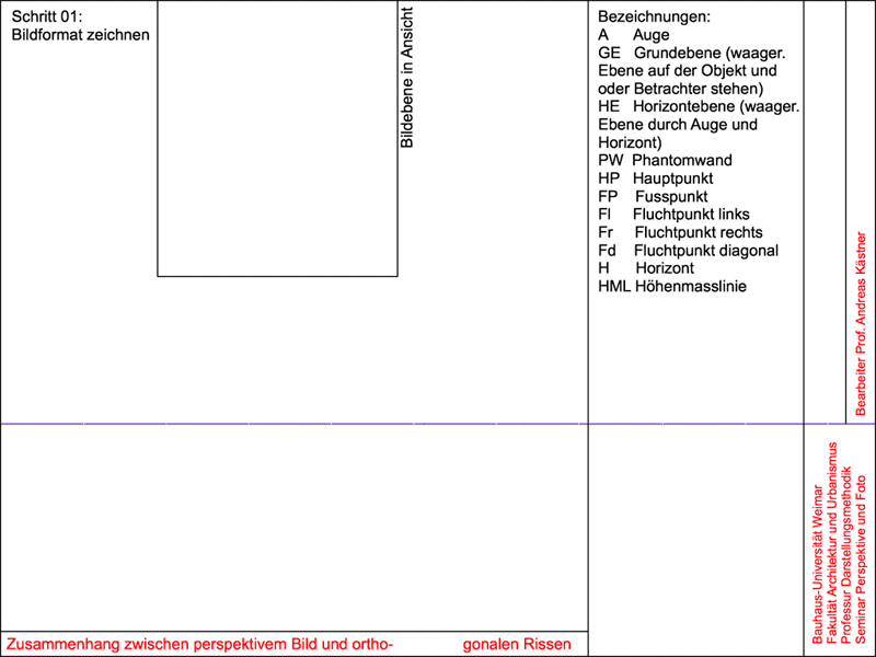
lesson 1: basics in perspective construction
lesson 2: reconstructing orthographic views from a photography with horizontally view (Bauhausmensa),
lesson 3: construction of a Cube in a perspective with 3 vanishing points
lesson 4: reconstructing the situation plans from fisheye distorted photography
lesson 5: creating the perspective birds view from a satellite photo
Each participant should generate a commented gif-animation of one of the exercises 1-5 (please decide yourself who makes which lesson). Remember, you can use the ArchiCAD layer functionality to generate the construction steps with it.
lesson 6: generating a3D-mass-model using a 2D-DWG-plan in C4D (result off a groups work (with several renderings 2048 * 1536 pixel)
7. calibrating a camera to a given photo or perspective view by using you own examples, (with several renderings 2048 * 1536 pixel)
Put all the content within a pdf-file. It would be great to present the gif-animations while our summary at 09. 07. I have five presentation panels 800 * 600 pixel which you could use for that. The rest could be delivered after winter semester start.
best regards
Prof. Andreas Kästner
lesson 7: callibrating a camera to a photo and getting the 3D-model
edit ~ 0 kommentare/fragen ~ 19. Mai 2015 11:24
;)
Hello P&F friends
here an example for your special situations.
- callibrate a new camera in c4D R16 (you can use the camera values in C4D R12 too)
- remove the kallibration nail to bring the camera in a correct height.
- generate a fitting cube for your building (you need the length of one edge to get the correct scale factor).
- undistorted the facades in photoshop and generate materials from them in C4D.
- transform the fitting cube to a polygon object and separate the two facade polygons to "frosted selections" an name them.
- apply the facade-materials to the facade ploygons by telling the materials, which poly-selection they are fore.
lesson 6: generating a3D-mass-model using a 2D-DWG-plan in C4D
edit ~ 0 kommentare/fragen ~ 10. Mai 2015 21:32
;)
;)
;)
;)
;)
Dear Seminar participants,
the dwg-fileonly contains 2d-informations. For it is not to be opened within C4D R12, I reconverted and saved it in ArchiCAD 18 under GAZA.dwg. Now you can use it in C4D R12.
After opening the browser shows a huge list of 2d-Objects. Using the layer-browser (Shift F4) make all layers invisible but not the buildings-layer. Now make some empty objects (for each quartier one). Fill the Quartiers with the fitting Polyline objects (each building has a polyline Object which contains 4 ore more polylines. Make a new layer for each quartier in the layer-manager.
In google earth have a look at the buildings shadow lengths to imagine the different building heights. For each quartier sort the polyline folders (building ground plans) into about three folders (one, two and three floors).
Converte all the Polyline folders of the same floor number to splines using the "Grundobjekte konvertieren" tool.
activate all splines of the same floor number and use the function "verbinden und löschen" (connect and delete) to make one multiple sprite object from them. Create an Extrude Nurbs object and put the connected sprite in it. Fill in the extrusions height (y-value of the Extrusions objects attributes) and delete the 200 in the Z-value to 0. Continue the last steps for each group of splines with different floor numbers.
The satellite foto as background picture into the ground view is already calibrated (without aspect automatic) with the cites dwg but will not appear till you load the hires background image into the ground views background. to do this download bayt-Hanun_left and -right to Photoshop to connect the two half images again. Make a new Material using the same background picture. Make a new Ebene-object and use the last created material for it and convert ist to a polyobject. Adjust the the sattelitefoto with the help of the Ground views background picture. Use the activated material tag of the Ebebe to fit the material size to the Ebene-object.
The polylines of the first 29 quartiers are already separated and converted into splines. The splines of quartier 25 are already added and extruded to 6m. The single splines are still there. Have a look to step 1-5 (quartier1) to learn how the workflow from dwg-polyline to C4D extrusion object runs.
These are the essential steps to generate a 3D-City model from a 2D dwg plan.
best regards
Prof. Andreas Kästner
lesson 5: creating the perspective birds view from a satellite photo
edit ~ 0 kommentare/fragen ~ 28. Apr 2015 16:36
;)
;)
;)
Hello Perspective freaks,
in our next lesson we will bring an object of interest from an orthographic satellite photo to a perspective view.
Best regards
Prof. Andreas Kästner
lesson 4: reconstructing the situation plans from fisheye distorted photography
edit ~ 0 kommentare/fragen ~ 24. Apr 2015 10:59
;)
;)
;)
Hello Persp.&Photo freaks,
here a preview to our next seminar. We will start preparing and analyzing a photo together before each of you will continue with its own material. there is a useful sequence of steps we should follow:
A Preparation of the Photo
1. optimizing the image will improve its contrast ore lighten dark zones
2. remoove distortions by using the lens correction filter (Objektivkorrektur) or alternatively image trends fisheye hemi 3 demo filter which you can download.
3. Use the filter "Konturen finden" (in Stilisierungsfilter) to get a very transparent image where you can determine object edges much better as in the originate photo.
4. Remoove the watermarks of the demo filter if nessecary.
B Analysis of the photos perspective
1. Find the main point MP of the Photo by intersecting its diagonales
2. Search for pairs of parallel object edges and draw them.
3. Start intersecting the longest pair at first to get its vanishing point..
4. Intersect the next pair to get a second vanishing point.
5. To get a vanishing line connect both vanishing points.
6. Draw a line from both vanishing points to the main point.
7. From each vanishing point draw a line perpendicular to one line of step 6.
8. Intersect the last two lines to get the third vanishing point.
C Reconstruction of the orthogonal views (side and ground) of the photographed objects
D Overlay the reconstructed fragments with a larger plan or satellite view to implement other fragments and reconstruct a wider ranged site.
E Generating a 3D model of the whole scenario with the topographical informations (DIM data).
This is very individual and depends on the special situation
best regards
Prof. Andreas Kästner
lesson 3b: construction of a cube in a perspective with 3 vanishing points
edit ~ 0 kommentare/fragen ~ 23. Apr 2015 08:56
;)
Hello perspective friends,
here comes the result of our last lesson as image. I hope all text is readable and there are no mistakes within the protocol.
best regards
Prof. A. Kästner
lesson 3: construction of a cube in a perspective with 3 vanishing points
edit ~ 0 kommentare/fragen ~ 15. Apr 2015 16:40
;)
hello participants of the seminar "Perspective and Photo
here I send you an example for a 3-point- perspective construction. The cubes edge in its left front was free defined. You should imagine the view onto a pyramid with three sides of orthogonal triangles. These three sides are layed down into the same layer as the pyramides bottom triangle. So one can see the perspective construction two side views (only one contains the cube) and the view of the ground from beneath.
Have a look to the view rays which come from horizon to the ground views eye to give the cube a fitting position. One can move the cube back or for, it will then shrink or grow for all cubes points always have to hold their positions on the view rays.
the cubes position in the side view can be found using two circles with VPL as center. Have a look to the view rays in side view that come from the cubes perspective image. The cubes edges that come from VPR are lengthened to the vanishing line between VPL and VPV. From there the view rays start tu the side views eye. They intersect the vertical edges of the cube and show, in which height the bottom and top faces of the cube are.
kind regards
Prof. Andreas Kästner