No edit summary |
No edit summary |
||
| Line 45: | Line 45: | ||
[[:File:martin_howse_circuit.ino]] | [[:File:martin_howse_circuit.ino]] | ||
'''video''' | |||
[https://youtube.com/shorts/j_NbcgJZpug?feature=share martin howse circuit experiment 1] | [https://youtube.com/shorts/j_NbcgJZpug?feature=share martin howse circuit experiment 1] | ||
[https://youtube.com/shorts/xGaSUHPxBko?feature=share martin howse circuit experiment 2 ] | [https://youtube.com/shorts/xGaSUHPxBko?feature=share martin howse circuit experiment 2 ] | ||
[https://youtube.com/shorts/7IoAyizJT3w?feature=share martin howse circuit experiment 3 ] | [https://youtube.com/shorts/7IoAyizJT3w?feature=share martin howse circuit experiment 3 ] | ||
Latest revision as of 18:28, 1 November 2022
Guide : http://triple-double-u.com/mycorrhizal-networks-or-how-i-hack-plant-conversations/
https://www.uni-weimar.de/kunst-und-gestaltung/wiki/File:Martin-howse.pdf
Hinweise
- AD620 chip has a 8 legs. And each of leg is defined as a number 1-8.
- Capacitor has a 2 legs like led. (+) goes to pin 4 of chip and (-) goes to pin 7 in this case.
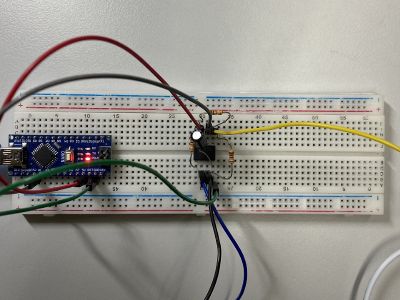
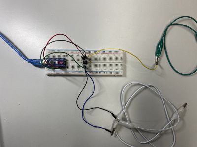
How to build Martin howse circuit on brettboard
1. Put the AD620 amplifier on middle of breadboard.
2. Place the 1 k Ω resistor between pin 1 and pin 8.
3. Connect capacitor is connected between pin 4 and pin 7.
4. Place the two 10 k Ω resistors. Both start from pin 5 (reference) with one ending at pin 7 (power, 5 V) and the other at pin 4 (earth, GND)
5. Pin 6 of the AD620 is connected to analog A0.
6. Connect the 3 cables on pin 2,3 and 5. (2,3 is for measuring value between A-B and 5 is for reference.
+white crocodiles are for measuring value and green one is for reference
Arduino part
arduino code
delay time = 100 is recommanded
video
martin howse circuit experiment 1

