No edit summary |
No edit summary |
||
| Line 177: | Line 177: | ||
[[File:carpet_switch_final.jpg]]<br><br><br> | [[File:carpet_switch_final.jpg]]<br><br><br> | ||
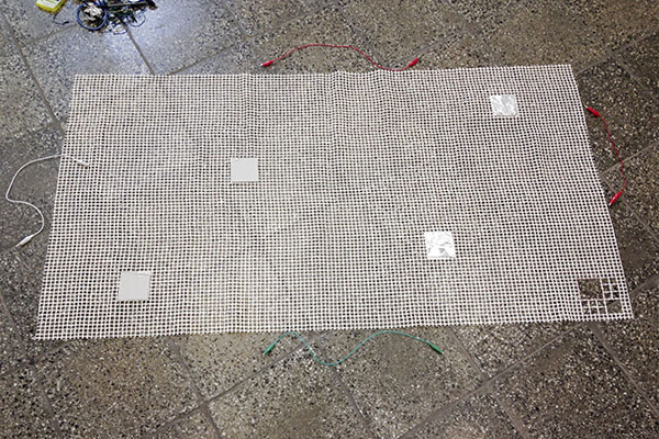
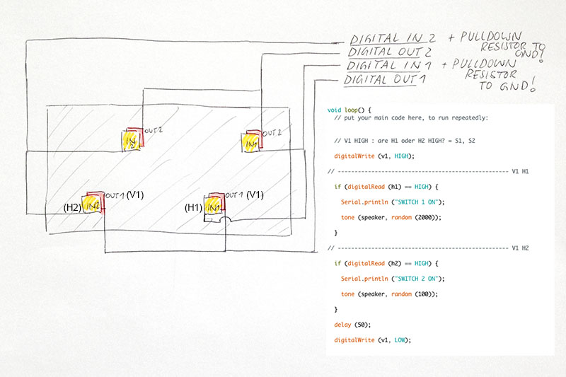
A larger set-up with 4 switches:<br><br> | A larger set-up with 4 switches and matrix-structure:<br><br> | ||
[[File:carpet_switch_proto.jpg]]<br><br> | [[File:carpet_switch_proto.jpg]]<br><br> | ||
[[File:carpet_switch_proto_circuit.jpg]]<br><br> | [[File:carpet_switch_proto_circuit.jpg]]<br><br> | ||
[https://vimeo.com/170147174 VIDEO] | [https://vimeo.com/170147174 VIDEO] | ||
Revision as of 10:46, 10 June 2016
Project Overview
I am interested in exploring different ways of interaction between humans and their everyday environment of things.
In this case I am focusing on the common activity of walking in connection with the carpet as a customizable floor covering.
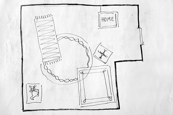
I want to create a carpet / a collection of carpets that sense people walking on it / them and then trigger a certain output as a response.
The minimum goal of this course is creating a single interactive carpet.
I would like to create a complex environment in which people have to move through the space in order to explore its different features.
Therefore I want to explore possibilities of creating an unpredictable output environment.
My technical interest consists of using a matrix structure to create a higher number of input options.
I accomplished different experiments in order to outline the needs of my final idea:
1) exploring touch sensor material
2) creating a simple button matrix / button resistor ladder
3) hacking a toy keyboard + exploring its inner architecture
4) reverse engineering and connecting a keyboard matrix with Arduino + exploring its functions
5) using different matrix systems as a) a resistive sensor and b) a switch based in- and output structure
6) trying out different ways of implementing switches in a carpet
This work is related to another project in which I designed a kind of yoga mat.
I did not yet include electronics in the mat because I am doubtful about the determined amount of switches and their pre defined outputs.
The interactive carpet is somehow an attempt to find out what happens if electronics are included and how the outputs can become unpredictable.
Technical implementation
I want to construct a matrix structure in order to use it as a sensor for peoples walking on it.
Therefore I want to build a certain number of switches that can handle the weight of a person standing on them.
The switches have to be made of a flexible material so that they automatically return to their „off-state“ when the person changes location.
I will try to implement a kind of resistor ladder in order to reduce the amount of input pins needed (this amount can easily become very high depending on the amount of sensors).
The outputs will be controlled by an Arduino Micro controller board.
It will trigger certain sounds/other outputs of sound/motion/.. devices.
Protoyping experiments
1) DIY Sensor Materials
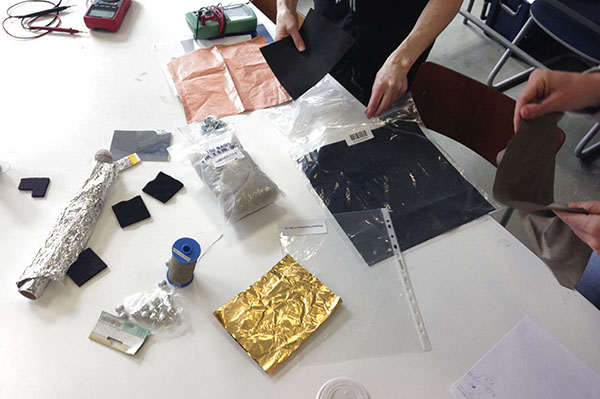
During the first hours we investigated different materials and their conductivity / resistivity.
I was mostly interested in materials that produce variable resistance when they are pushed and squeezed like „resistive plastic foam“.
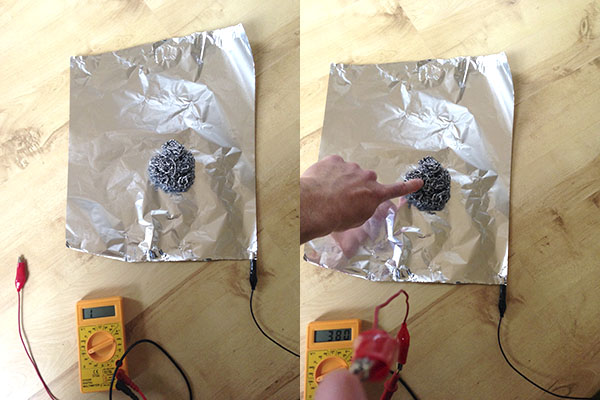
Another nice discovery was combining a metallic sponge and a piece of aluminium foil.
The outcome is a sensor that reacts to force.
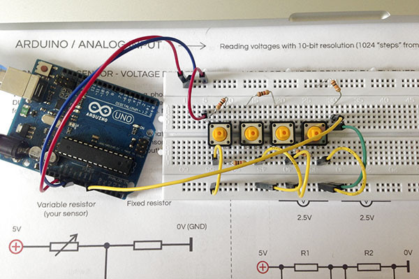
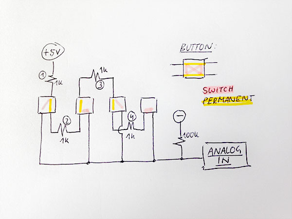
2) „Button Resistor Ladder“
The first experiment with matrix structures consists of buttons that are connected via a series of resistors.
The last resistor of that kind of „resistor ladder“ ends up in the analog pin of the arduino.
,
This way each button evokes a specific value in the analog input reading.
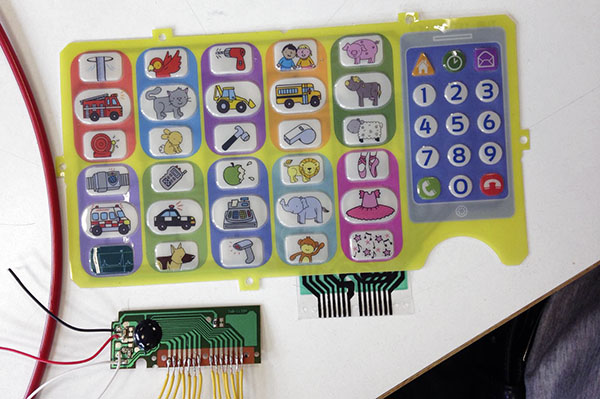
3) hacking a toy keyboard, triggering it with relays + exploring its inner architecture
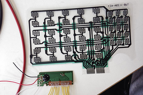
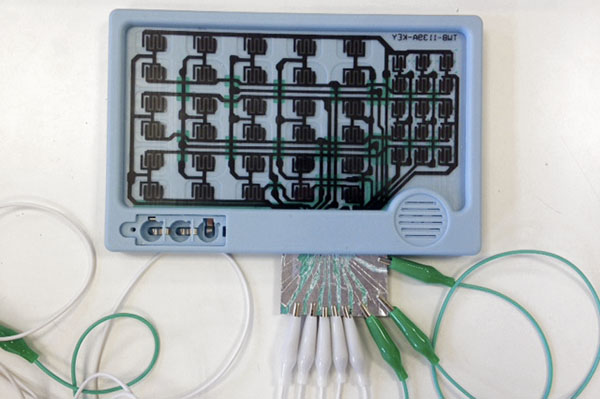
In the second experiment we took apart a toy that included a keyboard matrix to play a collection of sounds.
We traced each tone on the matrix and soldered external wires to the sound terminals.
This allowed us to access the sounds by using another switching concept in order to trigger each sound.
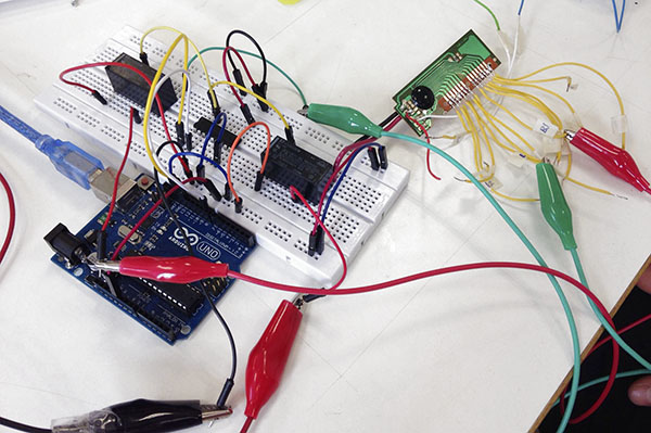
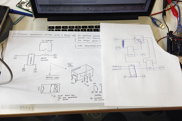
We chose relays as our main switches and connected them to the sound device.
The relays were connected to the arduino and we were able to trigger and cut off single sound files coming out of the toy electronics.
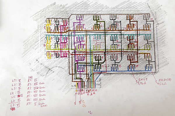
I then decided to explore the matrix of the toy keyboard a little further.
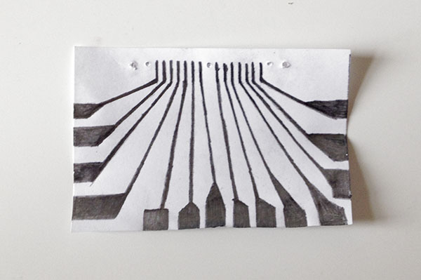
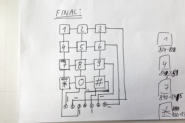
A drawing helped me to understand and trace the switches of each bottom connector.
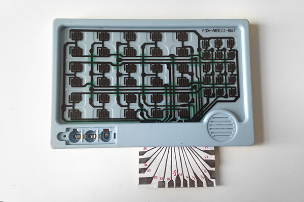
I then attached an extension in order to access the bottom connectors.
3) hacking a toy keyboard, triggering it with relays + exploring its inner architecture
This is a common keyboard matrix with a 4 x 3 buttons number plate.
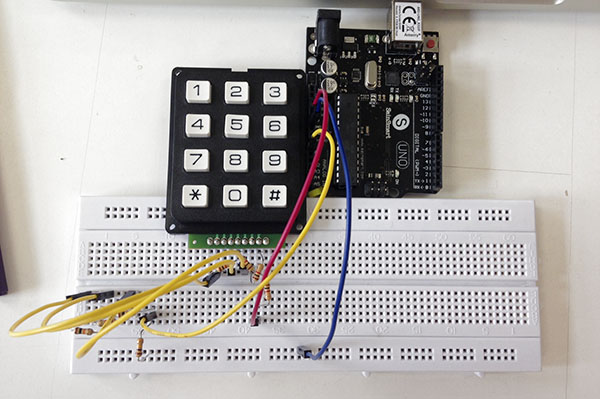
I „reverse engineered“ the matrix structure (hidden in the case) after I soldered pin headers to its connectors in order to plug it into the bread board.
I was mostly interested in using the matrix as a variable resistor rather than using it as a „multiple digital pin input device“.
I achieved that by connecting different resistor values in between each contact of the vertical and the horizontal button lines.
In the end a voltage divider helped to create different voltage changes for the arduinos analog input.
The matrix is actually meant to be used as a "multiple digital pin input / output interface" like shown on this website.
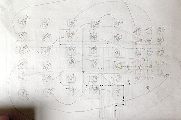
This way every button represents a certain value in the analog input of the arduino.
By doing that I discovered a major problem: some of the values almost overlapped. In addition to the arduinos analog input pin generated quite some noise.
Therefore I had to define a certain range of values for each button. Although this worked a bit better there was still a lot of overlap.
This overlap sometimes lead to the effect that the interpretation of buttons being pressed was wrong.
Another interesting part of that experiment was the code.
I did not use any library - instead of that I tried to use my basic programming skills to set it up by myself.
It surprisingly worked out quite well - despite the mentioned overlap problem and the face that I needed a lot of memory.
In order to solve these issues in the future I need to learn about programming „arrays“ and „for-loops“ that can help minimizing the amount of code.
The overlap problem could be solved by using binary functions / average measurements that define clearer value states.
5) using different matrix systems as a) a resistive sensor and b) a switch based in- and output structure
The idea of using a matrix as a variable resistor was a good way of connecting the toy-keyboard to the arduinos analog input.
My hacked version of the toy keyboard does not really work as a system of clear state switches as I rather used a resistive than a conductive material in order to access the matrix (graphite lines).
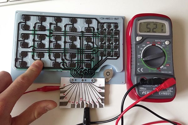
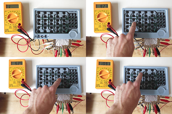
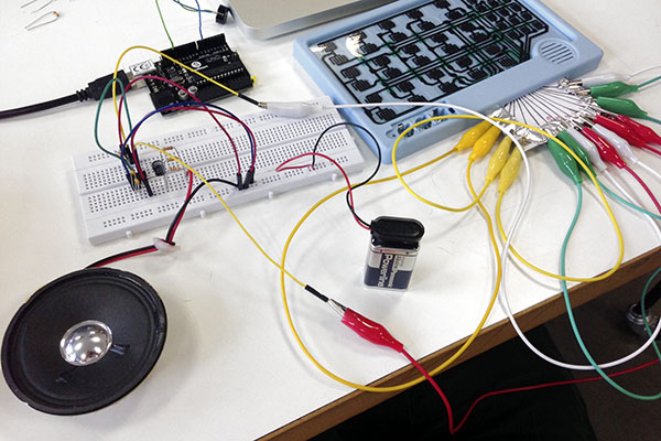
The multimeter shows that - if I combine all the vertically and all the horizontally connected „lines“ together - I get a certain value of resistance for each button.
This way it is possible to use the matrix for instance as a variable resistor for an astable 555 timer chip between pin 6 and pin 7:
6) trying out different ways of implementing switches in a carpet
The final idea of my matrix explorations is to implement a similar structure in our everyday environment.
I want to use a carpet as the main interface object as it is 1) feasible and 2) something casual that is used in almost every household.
The first problem is to install switches inside / underneath the carpet.
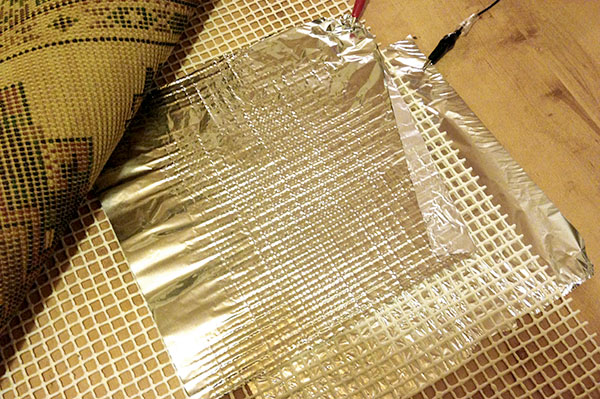
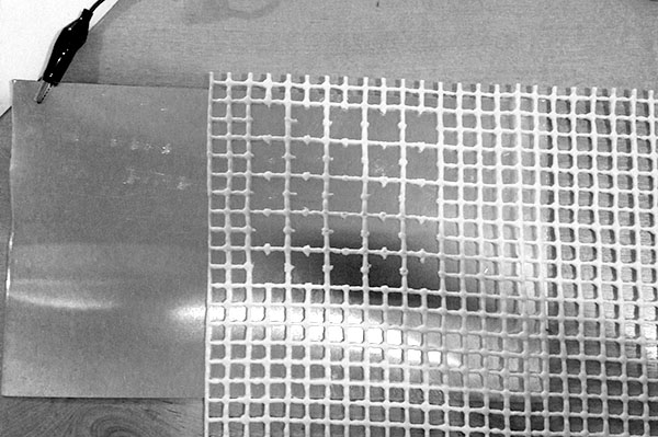
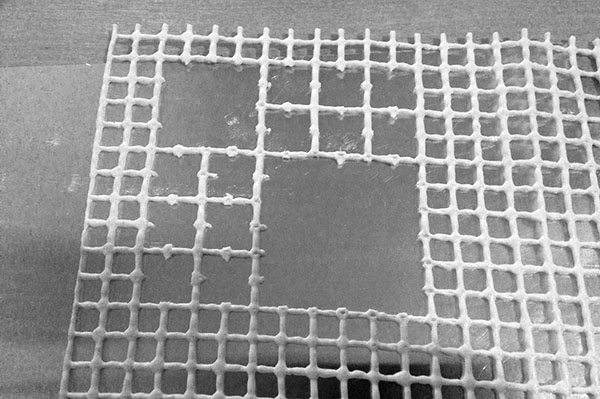
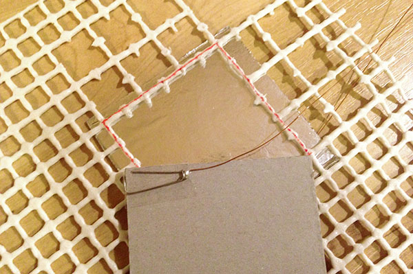
The initial idea is to use an anti-sliding mat as a grid that separates the contacts of the switches.
It is a very flexible material that is easy to manipulate without the need of professional tools.
Another problem is the material that is used to build the switches.
It needs to be 1) flexible (coming back into its original form) and 2) conductive.
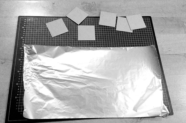
I experimented with different materials such as aluminium foil, aluminium plates and a conductive sponge.
It turned out that a piece of cardboard covered with aluminium foil is the best way to fulfill both goals.
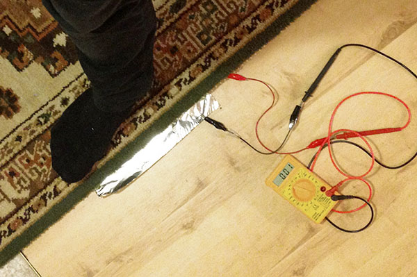
I also discovered that the size of the gaps inside the flexible grid plays a big role in connection to the performance of the „cardboard-alu switches“.
I tried out different sizes until I found a size that fit to the average „size of a footstep“.
