No edit summary |
|||
| (4 intermediate revisions by one other user not shown) | |||
| Line 12: | Line 12: | ||
built circuit | built circuit | ||
<videoflash type="vimeo">134186394|800|530</videoflash> | |||
| Line 33: | Line 37: | ||
schematic diagram | schematic diagram | ||
[[File:file. | |||
[[File:file.switch-circuit built.jpg]] | |||
built circuit | built circuit | ||
[[File: | |||
<videoflash type="vimeo">134191176|800|530</videoflash> | |||
Switches: | |||
The switch circuit is built using a piezo as a form of switch. FIn the circuit, the piezo is connected to the output pin. When the piezo is used (by clapping it on the hand) the LED turns on for 15 seconds. | |||
===Assignment 3=== | |||
[[File:Kreislauf2.jpg|left|Berry Boat]] | |||
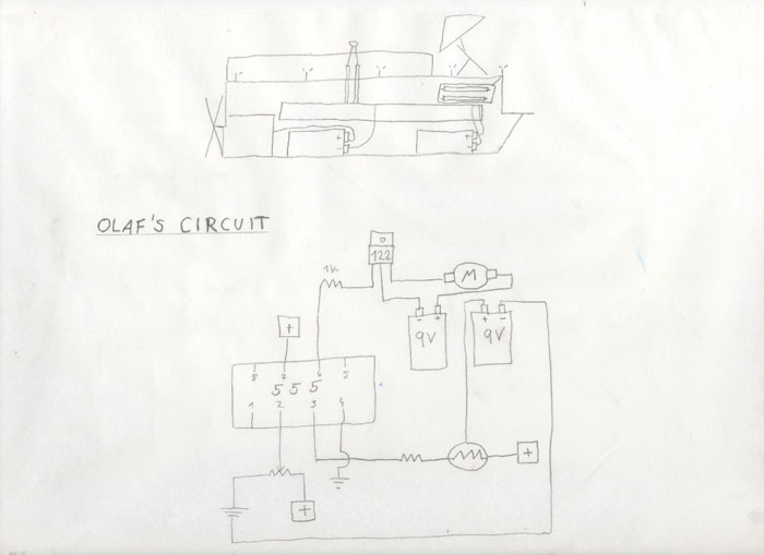
[[File:Kreislauf3.jpg|Olafs Boat]] | |||
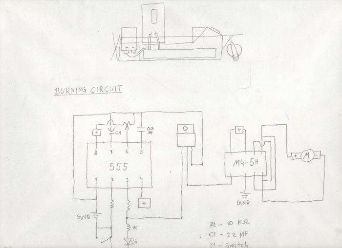
[[File:Kreislauf4.jpg|left|Burning Circuit]] | |||
<videoflash type="youtube">DlxO6fPegbs|700|450</videoflash> | |||
Latest revision as of 12:28, 23 July 2015
Introduction to Electronics
Assignment 1
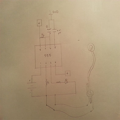
schematic diagram
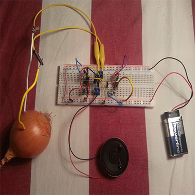
built circuit
<videoflash type="vimeo">134186394|800|530</videoflash>
Modulation Circuit:
For the modulation circuit, different resistors and capacitors were used to get the different resistance from different objects in the form of sound.
Assignment 2
schematic diagram
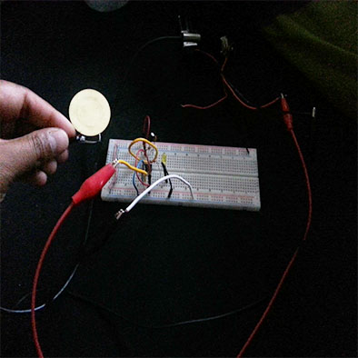
built circuit
<videoflash type="vimeo">134191176|800|530</videoflash>
Switches:
The switch circuit is built using a piezo as a form of switch. FIn the circuit, the piezo is connected to the output pin. When the piezo is used (by clapping it on the hand) the LED turns on for 15 seconds.
Assignment 3
<videoflash type="youtube">DlxO6fPegbs|700|450</videoflash>

